


36
TK-782
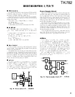
Fig. 4 AF signal system /
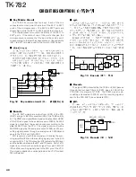
Fig. 3 Wide/Narrow changeover circuit
"
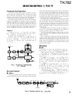
Wide/Narrow Changeover Circuit
The W/N port (pin 11) of the shift register (IC7) is used to
switch between ceramic filters. When the W/N port is high,
Q24 turns on and the ceramic filter SW diode (D22, D23) CF1
turns on to receive a Wide signal. At the same time, Q16
turns on and one of the filters is selected so that the wide
and narrow audio output levels are equal.
When the W/N port is low, Q23 turns on and the ceramic
filter SW diode (D22, D23) CF2 turns on to receive a Narrow
signal.
"
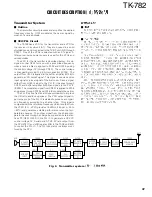
AF Signal System
The detection signal (DEO) from the TX-RX unit (A/2) goes
to the audio processor (IC504) of the TX-RX unit (B/2). The
signal passes through a filter in the audio processor to ad-
just the gain, and is output to IC502. IC502 sums the AF
signal and the DTMF signal and returns the resulting signal
to the TX-RX unit (A/2). The signal (AFO) sent to the TX-RX
unit (A/2) is input to the D/A converter (IC5). The AFO output
level is adjusted by the D/A converter. The signal output from
the D/A converter is added with the BEEP signal (BPO) and
the resulting signal is input to the audio power amplifier (IC10).
The AF signal from IC10 switches between the internal
speaker and speaker jack (J1) output.
"
"
CF1
(Wide)
CF2
(Narrow)
IFI
MXO
IC11
IF system
AFO
DET
OUT
C107
C100
C108
R114
R123
R133
R126
R125
R130
R131
+
+
Q16
DM
Q32 R121
W/N
IC7 11pin
Wide : H
Narrow : L
C118
D22
D23
Q23
5C
Q24
Wide : L
Narrow : H
AUDIO
PROCE.
SUM
AMP
D/A
CONV.
IC504
IC502
IC5
AF PA
IC10
SP
DTMF
BPO
AFO
DEO
TX-RX UNIT (B/2) : Control section
CIRCUIT DESCRIPTION /
"
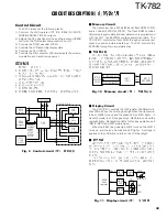
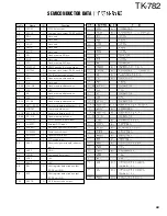
Squelch Circuit
The detection output from the FM IF IC (IC11) is amplified
by IC2 and the signal (DEO) is sent to the TX-RX unit (B/2).
The signal passes through a high-pass filter and a noise am-
plifier (Q503) in the TX-RX unit (B/2) to detect noise. A volt-
age is applied to the CPU (IC511). The CPU controls squelch
according to the voltage (ASQ) level. The signal from the
RSSI pin of IC11 is monitored. The electric field strength of
the receive signal can be known before the ASQ voltage is
input to the CPU, and the scan stop speed is improved.
"
Fig. 5 Squelch circuit /
IC2
AMP
IC503
AMP
Q503
NOISE AMP D509
IC11
IC511
DEO
RSSI
HPF
DET
CPU
IF
SYSTEM
TX-RX UNIT (B/2) : Control section
Содержание TK-782
Страница 64: ...TK 782 1 8 1 BLC 2 PSB 3 E 4 PTT 5 ME 6 MIC 7 HOOK 8 CM 63 ...
Страница 68: ...TK 782 67 ...
Страница 70: ...TK 782 69 ...
Страница 72: ...TK 782 71 ...
Страница 74: ...TK 782 73 ...
Страница 76: ...TK 782 75 ...
Страница 78: ...TK 782 77 ...
Страница 87: ...TK 782 TK 782 TK 782 99 BLOCK DIAGRAM ...