background image

TK-7100

10

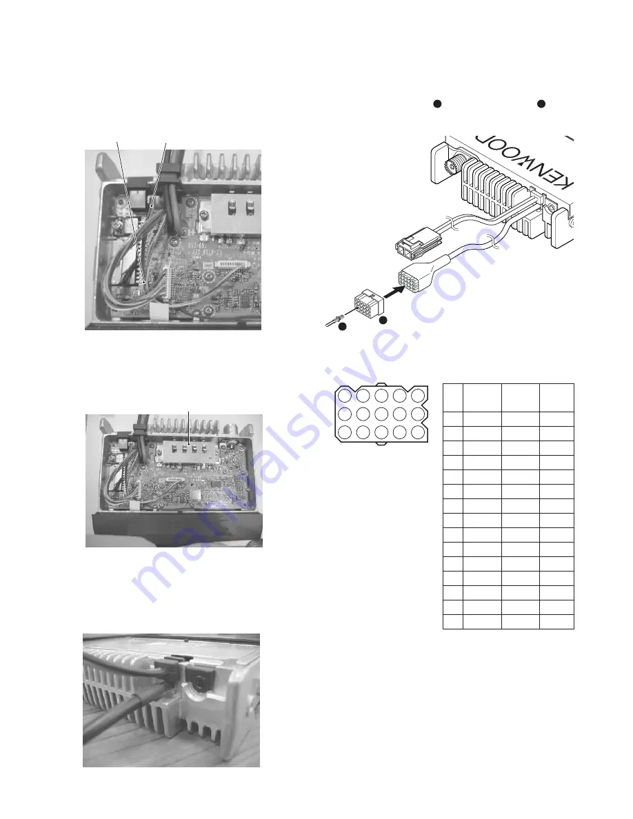
7. Align the terminal B KCT -39 cable underneath the termi-

nal A cable align the speaker cable (T07 -1082 -05) below
both KCT-39 cables.

Speaker cable

In this direction

8. Align all cable to the left side so as to avoid the Power

Module Area. Mount the shielding cover and secure it
with the five M2.6 screws.

Power module

9. After everything has been properly mounted, the KCT-39

sumi tube should look similar to that as shown in the dia-
gram below.

Exterior back view of KCT-39

1

2

13
15

1

3

10. Connect the KCT-39 to the external accessory by insert-

ing the crimp terminal (

1

) into the square plug (

2

), both

of which are supplied with the KCT-39.

1

4

7

10

13

2

5

8

11

14

3

6

9

12

15

No.

Color

Internal

Name

connector

1

Red

CN2-1

SB

2

Pink

CN3-1

IGN

3

Black

CN2-3

GND

4

Brown

CN3-3

DETO

5

Orange

CN3-2

DATAI

6

Yellow

CN2-8

FNC4

7

Green

CN2-7

FNC3

8

Blue

CN2-9

FNC5

9

Purple

CN2-12

FNC8

10

Gray

CN2-10

FNC6

11

White

CN2-11

FNC7

12

NC

NC

13

NC

NC

14

Sky blue

CN2-6

FNC2

15

Turquoise

CN2-5

FNC1

 Accessory Port Function

REALIGNMENT

Fig. 3

Содержание TK-7100

Страница 1: ... SYSTEM SET UP 3 OPERATING FEATURES 4 REALIGNMENT 5 INSTALLATION 11 DISASSEMBLY FOR REPAIR 14 CIRCUIT DESCRIPTION 17 SEMICONDUCTOR DATA 22 COMPONENTS DESCRIPTION 23 PARTS LIST 24 EXPLODED VIEW 30 PACKING 31 ADJUSTMENT 32 PC BOARD DISPLAY UNIT X54 3430 20 36 TX RX UNIT X57 6910 XX 38 SCHEMATIC DIAGRAM 42 BLOCK DIAGRAM 46 LEVEL DIAGRAM 48 TERMINAL FUNCTION 50 SPECIFICATION 51 CONTENTS ...

Страница 2: ...quired to install or operate the radio 3 PRE INSTALLATION CHECKOUT 3 1 Introduction Each radio is adjusted and tested before shipment How ever it is recommended that receiver and transmitter opera tion be checked for proper operation before installation 3 2 Testing The radio should be tested complete with all cabling and accessories as they will be connected in the final installation Transmitter f...

Страница 3: ...ircuit board views and align ment procedures contained in this manual Speaker jack cap Power input connector Antenna connector NOTE If you do not intend to use the 3 5 mm jack for the external speaker fit the supplied speaker jack cap to stop dust and sand from getting in Merchandise received License and frequency allocated by FCC Choose the type of transceiver Transceiver programming KCT 39 Conne...

Страница 4: ...ation 1 3 Display Indicator Description Appears while transmitting Appears when trunking is activated Appears while monitoring the selected channel squelch is off Appears when making a call using Code Squelch or Selective Call Appears and blinks when receiving a Code Squelch call Appears while scanning Appears when the AUX port has been activated or when the Scrambler function has been selected Ap...

Страница 5: ...mming interface cable Option The KPG 46 is required to interface the TK 7100 to the computer It has a circuit in its D subconnector 25 pin case that converts the RS 232C logic level to the TTL level The KPG 46 connects the modular microphone jack of the TK 7100 to the computers RS 232C serial port 3 4 Programming Software Description KPG 80D is the programming software for TK 7100 sup plied on thr...

Страница 6: ... programming mode cannot be set when it has been disabled with the FPU 5 3 Channel Setting Mode Each channel can be setup in its action mode by using the panel keys Pressing MON when SELF is displayed sets chan nel setting mode Select an item set using then change the selection with the CH UP or CH DOWN The data displayed using SCN is stored in the memory and then proceeds to the next item Pressin...

Страница 7: ...t used when option signalling is none QT DQT Not used when option DTMF signalling is none 7 Busy Off Default channel Carrier lockout QT DQT If QT DQT decode is not set it cannot be selected DTMF If option signalling is set to off it cannot be selected 8 Beat No Default Yes 9 RF High power Default power Low power 10 Wide Wide Default Narrow Narrow 11 Scan Delete Del Add Add Default 12 Priority No D...

Страница 8: ... 0 5 seconds Display of the current setting Input the code with DTMF key only key Set to default data Finish beep will sound when displayed data is stored 1 ID code range is from 3 to 4 digits when selective call is selected Self programming mode MON MON SCN Channel setting mode Channel selection Group selection RX frequency Change frequency step Blank Change frequency step Hold MON MON MON MON MO...

Страница 9: ... cord 3 Attach a new cushion G13 1960 08 to the DC bush Cushion 4 Place the KCT 39 sumi tube along the chassis and insert the cable tie into the TX RX PCB slot as shown in the dia gram below Insert the cable tie into the slot here KCT 39 sumi tube 5 Align the KCT 39 cable to the left side of the DC cord then place the DC cord back into its slot along the chassis over the top of the KCT 39 sumi tub...

Страница 10: ... that as shown in the dia gram below Exterior back view of KCT 39 1 2 13 15 1 3 10 Connect the KCT 39 to the external accessory by insert ing the crimp terminal 1 into the square plug 2 both of which are supplied with the KCT 39 1 4 7 10 13 2 5 8 11 14 3 6 9 12 15 No Color Internal Name connector 1 Red CN2 1 SB 2 Pink CN3 1 IGN 3 Black CN2 3 GND 4 Brown CN3 3 DETO 5 Orange CN3 2 DATAI 6 Yellow CN2...

Страница 11: ...tting With the KPG 80D Select External Devices from the Edit menu and en able the Ignition Sense Fig 4 2 1 13 15 1 3 R71 CN2 TX RX unit Component side Fig 5 1 Optional Board 1 1 Voice Scrambler Board Connection Modification 1 Remove the cabinet and shielding cover from the trans ceiver 2 Delete R202 and R267 on the TX RX unit A 9 8 7 D C B A A12 1 3 7 8 9 10 11 12 1 12 B A11 C A10 D A9 E 1 2 3 4 5...

Страница 12: ...ted subsequent to the de emphasis circuit Cushion G13 1963 04 Cushion G13 1964 04 Voice scrambler board Front side to CN2 and CN3 to CN2 and CN3 CN3 Voice scrambler board CN2 TX RX UNIT Component side Fig 3 2 SmarTrunk 1 Unscrew the five M2 6 screws N87 2614 46 then re move the shielding cover F10 2491 03 M2 6 screws Shielding cover 2 The SmarTrunk Board is to be mounted in the silk screened area ...

Страница 13: ...n the variable resistor R18 and the capacitor C19 then place the supplied in sulation sheet over the integrated circuit IC Variable resistor IC Cushion F Part No G13 2006 04 Capacitor Insulation sheet 7 Adhere the 10 x 10 x 2 5 mm cushion E G13 2007 04 and the supplied 20 x 20 x 1mm cushion C to the under side of the ST 865KW4 as shown in the diagram below Cushion E Part No G13 2007 04 Cushion C N...

Страница 14: ...nd ST 865KW4 are available from SmarTrunk Systems Inc Setting With the KPG 80D Select External Devices from the Edit menu and set the SmarTrunk INSTALLATION DISASSEMBLY FOR REPAIR 1 When you remove the panel turn the transceiver up side down Detach the panel by lifting the tabs as shown be low 2 To remove the cabinet first turn the transceiver up side down Detach the cabinet by prying the tabs as ...

Страница 15: ...ew driver is needed as illustrated q Open the bottom of display unit at No 3 as indicated Open the bottom of display unit at No 2 as indicated w e Open the top of display unit at No 4 as indicated r Lift up the display unit and remove t 4 2 Mount the display unit To mount the display unit on the panel follow the correct procedures shown to ensure easy display unit assembly and good fitting onto th...

Страница 16: ... REPAIR w Snap in top of display unit No 4 e Snap in bottom of display unit No 1 Snap in bottom of display unit No 2 r t Snap in bottom of display unit No 3 Ensure that display unit holes locator is properly located on the illumination guide locators as shown y u ...

Страница 17: ...STEM PLL VCO 16 8MHz 50 4MHz ANT RX TX SP MIC 1 2 Fig 1 Frequency configuration IF Amplifier The first IF signal is amplified by Q351 and the enters IC301 FM processing IC The signal is heterodyned again with a second local oscillator signal within IC301 to create a 450kHz second IF signal The second IF signal is then fed through a 450kHz ceramic filter Wide CF301 Narrow CF302 to further eliminate...

Страница 18: ... IC251 IC161 W NO EVOL2 AF PA IC252 SP IF IC IC301 Q301 NOISE AMP D301 IC301 IC101 AFO RSSI DET CPU IF SYSTEM SQIN RSSI Fig 3 Wide Narrow switching circuit Fig 4 AF signal system Fig 5 Squelch circuit PLL Frequency Synthesizer The PLL circuit generates the first local oscillator signal for reception and the RF signal for transmission PLL The frequency step of the PLL circuit is 5 or 6 25kHz A 16 8...

Страница 19: ...anted high frequency harmonic com ponents and the resulting signal is goes the antenna termi nal APC Circuit The automatic transmission power control APC circuit detects the power amplifier IC502 output with a diode D606 D607 and applies a voltage to IC501 IC501 com pares the APC control voltage PC generated by the D A con verter IC161 and DC amplifier IC203 with the detection output voltage IC501...

Страница 20: ... ports are always low The microprocessor monitors the status of the KMI1 to KMO2 ports If the state of one of the ports changes the microprocessor assumes that the key at the matrix point cor responding to that port has been pressed Encode The QT and DQT signals are output from QT DQT of the CPU IC101 and summed with the external pin DI line by the summing amplifier IC203 and the resulting signal ...

Страница 21: ... Fig 16 Power supply circuit CIRCUIT DESCRIPTION Power Supply Circuit When the power switch on the display unit is pressed the power port on the display unit which is connected port 17 POWER goes low then port 82 SBC goes high Q32 turns on SB SW Q31 turns on and power SB is supplied to the radio When the DC power supplied to the radio the voltage regulator IC IC33 supply into the CPU VDD and reset...

Страница 22: ...rt 3 44 CEFLS I O CE for flash 45 46 FNC4 FNC5 I O Function port 4 5 47 48 FNC7 FNC6 I O Function port 7 6 49 FNC8 I O Function port 8 50 AFM O AF mute 51 SPM O Speaker mute Pin No Name I O Function 52 AMPSW O AF AMP switch 53 DT O Common data 54 CK O Common clock 55 56 NC I 57 59 DST1 DST3 I Destination 1 3 60 VCC 5V 61 NC I 62 VSS GND 63 NC I 64 NARROW O 65 WIDE O 66 68 NC I 69 CL O Clock for LC...

Страница 23: ...ergency MIC mute Q202 FET Emergency MIC mute Active when MICEM is H Ref No Parts name Description Q251 Transistor Buffer amplifier RX audio Q252 253 FET AF mute Active while AFM is H Q254 Digital transistor AF mute Active while SPM is H Q255 Transistor AF mute Active while AMPSW is H Q301 Transistor Noise amplifier SQL amplifier Q302 Transistor Buffer amplifier 16 8MHz 3rd over tone Q351 Transisto...

Страница 24: ...25 2320 04 PROTECTION BAG 43 3D H52 1699 12 ITEM CARTON CASE M 43 D H52 2032 02 ITEM CARTON CASE M2 K 45 1C J19 1584 05 MIC HOLDER ACCESSORY K 46 1D J29 0662 03 BRACKET ACCESSORY 48 3A K29 9262 01 KEY TOP A 2B N67 3008 46 PAN HEAD SEMS SCREW W B 2B 3B N87 2606 46 BRAZIER HEAD TAPTITE SCREW C 1B 2B N87 2614 46 BRAZIER HEAD TAPTITE SCREW 50 1C N99 0395 05 SCREW SET ACCESSORY 52 3A T07 0739 05 SPEAKE...

Страница 25: ...TAN 4 7UF 6 3WV C252 CC73GCH1H390J CHIP C 39PF J C253 254 CK73GB1A105K CHIP C 1 0UF K C255 CK73GB1H822K CHIP C 8200PF K C256 CK73GB1E183K CHIP C 0 018UF K C257 CK73GB1C393K CHIP C 0 039UF K C258 261 CK73GB1H103J CHIP C 0 010UF J C262 CK73GB1H102K CHIP C 1000PF K C263 264 CK73GB1C333K CHIP C 0 033UF K C265 266 CK73GB1C104K CHIP C 0 10UF K C267 CK73GB1A474K CHIP C 0 47UF K C268 CK73GB1C104K CHIP C 0...

Страница 26: ...30B CHIP C 3 0PF B C456 CC73GCH1H020B CHIP C 2 0PF B C457 CK73GB1H102K CHIP C 1000PF K C458 CK73GB1H221K CHIP C 220PF K C459 CK73GB1H102K CHIP C 1000PF K C460 CC73GCH1H180J CHIP C 18PF J C461 CK73GB1H102K CHIP C 1000PF K C462 CC73GCH1H100C CHIP C 10PF C C463 464 CK73GB1H102K CHIP C 1000PF K C465 CC73GCH1H220J CHIP C 22PF J C466 CC73GCH1H101J CHIP C 100PF J C467 CK73GB1H102K CHIP C 1000PF K C468 CK...

Страница 27: ...J 1 16W R41 RK73GB1J334J CHIP R 330K J 1 16W R61 RK73GB1J471J CHIP R 470 J 1 16W R62 RK73GB1J102J CHIP R 1 0K J 1 16W R66 67 RK73GB1J473J CHIP R 47K J 1 16W R68 69 RK73GB1J102J CHIP R 1 0K J 1 16W R70 RK73GB1J473J CHIP R 47K J 1 16W R71 RK73GB1J472J CHIP R 4 7K J 1 16W R72 RK73GB1J105J CHIP R 1 0M J 1 16W R73 RK73GB1J104J CHIP R 100K J 1 16W R74 RK73GB1J473J CHIP R 47K J 1 16W R75 RK73GB1J102J CHI...

Страница 28: ...47K J 1 16W R350 RK73GB1J273J CHIP R 27K J 1 16W R351 RK73GB1J471J CHIP R 470 J 1 16W R352 RK73GB1J101J CHIP R 100 J 1 16W R353 RK73GB1J104J CHIP R 100K J 1 16W R354 RK73GB1J331J CHIP R 330 J 1 16W R355 RK73GB1J471J CHIP R 470 J 1 16W M K R355 356 RK73GB1J102J CHIP R 1 0K J 1 16W M2 R356 RK73GB1J102J CHIP R 1 0K J 1 16W M K R358 RK73GB1J470J CHIP R 47 J 1 16W R359 RK73GB1J224J CHIP R 220K J 1 16W ...

Страница 29: ...A221 DIODE D31 ZSH5MA27 SURGE ABSORBER D32 1812L110PR VARISTOR D61 02DZ18 X Y ZENER DIODE D201 DAN222 DIODE D202 1SS372 DIODE D251 MA742 DIODE D301 MA742 DIODE D302 303 DAN222 DIODE D351 354 HVC350B VARIABLE CAPACITANCE DIODE D401 MA2S111 DIODE D402 HZU5ALL DIODE D403 406 MA2S304 VARIABLE CAPACITANCE DIODE D407 MA360 VARIABLE CAPACITANCE DIODE D408 MA2S111 DIODE D409 DAN235E DIODE D501 1SS355 DIOD...

Страница 30: ...B B Part name label face down Display unit A M3 x 8 N67 3008 46 B M2 6 x 6 Br Tap N87 2606 46 C M2 6 x 14 Br Tap N87 2614 46 1 34 21 22 26 IC502 20 13 36 25 10 2 30 8 15 48 14 52 35 3 6 11 5 Q31 IC252 701 S No label Parts with the exploded numbers larger than 700 are not supplied ...

Страница 31: ...er packing case H02 0617 02 53 Microphone T91 0624 05 K 39 Polystyrene foamed fixture H10 6636 13 42 Protection bag H25 2320 04 41 Protection bag H25 0103 04 40 Polystyrene foamed fixture H10 6639 03 43 Item carton case H52 1699 12 M H52 2032 02 M2 K 7 Instruction manual B62 1778 00 B62 1779 00 M2 K Parts with the exploded numbers larger than 700 are not supplied ...

Страница 32: ...z or more Output 0 to 1V 10 Distortion Meter Capability 3 or less at 1kHz Input Level 50mV to 10Vrms 11 4Ω Dummy Load Approx 4Ω 10W or more 12 Regulated Power Supply 13 6V approx 20A adjustable from 9 to 17V Useful if ammeter requipped 13 Spectrum Analyzer Center frequency 50KHz to 600MHz 14 Tracking Generator Output Voltage 100mV or more Tuning cable E30 3383 05 Adapter cable E30 3383 05 is requi...

Страница 33: ...ore mounting the shield cover as below Fuse To mount the fuse the cable terminal direction must be as follow Locator Speaker cable This side up This side up Cable terminal Cable terminal Fuse Pin 1 marker Part name label face down TX RX unit Component side IC252 Power Volume up down Display Channel up down Speaker MIC jack MON SCN keys RESET CNVSS 5M B E TEMP2 POWER TXD RXD CV IGN 8T BPF AFV TEMP1...

Страница 34: ...ltage DC Power supply terminal 13 6V 2 VCO lock 1 CH TX high Digital voltmeter CV TC402 5 5V 0 1V voltage 2 CH RX high TC401 5 5V 0 1V 3 CH TX low Check 0 7V or more 4 CH RX low 3 IF coil 1 CH RX center Wide SSG AFV L301 3 25 3 35V DC 2 SSG output 53dBm 501µV Digital voltmeter Mod 1kHz Dev 3kHz 4 RF 1 CH RX center Wide Track generator ANT TC351 Adjust the BPF waveform bandpass CH RX low Wide Spect...

Страница 35: ...form as below balance CH TX center Wide Narrow or Linear detector CH TX high Wide LPF 3kHz 2 Transmit Oscilloscope 6 MAX 1 CH TX low Wide Modulation analyzer ANT 4 0kHz Wide 50Hz balance CH TX center Wide Narrow or Linear detector MIC 2 0kHz Narrow CH TX high Wide LPF 15kHz According to the large 2 AG 1kHz 50mV Oscilloscope 3 Transmit AG 7 MIC 1 CH TX center Wide Narrow AF V M Check 3kHz 0 2kHz se...

Страница 36: ... SEG13 SEG12 SEG11 SEG10 SEG9 SEG8 SEG7 SEG6 SEG5 SEG4 D24 D25 D28 D29 D30 D31 J1 LCD C22 C23 C24 C25 C30 C31 Q10 Q11 1 3 4 5 C6 D D18 D27 IC2 R11 R21 R22 R23 R24 R25 R26 Q6 Q9 B C E R33 R34 R36 R37 R38 R39 R40 CP1 C15 C16 C18 C19 HOOK CM PTT MIC SB MBL GND ME 1 12 13 24 25 36 37 48 DISPLAY UNIT X54 3430 20 Component side view J72 0885 09 DISPLAY UNIT X54 3430 20 Foil side view J72 0885 09 TK 7100...

Страница 37: ...10 R24 R4 R5 R6 R7 R8 R9 CN1 CP1 1 18 DISPLAY UNIT X54 3430 20 Component side view J72 0885 09 DISPLAY UNIT X54 3430 20 Foil side view J72 0885 09 Ref No Address D2 3N D3 3C D4 7K D5 7G D19 3H D20 3I D21 3J D22 3K Ref No Address D23 4H D24 4I D25 4J D26 4K D28 3F D29 4F D30 4G D31 3G Ref No Address IC2 11I Q6 11C Q9 11F Q10 11C Ref No Address Q11 12E D17 12J D18 12D D27 11B PC BOARD TK 7100 Compon...

Страница 38: ... C4 C6 D17 D18 D27 L1 IC2 R10 R11 R21 R22 R23 R24 R25 R26 Q6 Q9 B C E R33 R34 R36 R37 R38 R4 R39 R5 R6 R7 R8 R9 R40 CN1 CP1 C15 C16 C18 C19 HOOK CM PTT MIC SB MBL GND ME 1 12 13 24 25 36 37 48 1 18 DISPLAY UNIT X54 3430 20 Component side view J72 0885 09 DISPLAY UNIT X54 3430 20 Component side view J72 0885 09 DISPLAY UNIT X54 3430 20 Foil side view J72 0885 09 DISPLAY UNIT X54 3430 20 Foil side v...

Страница 39: ...151 C152 Q202 R61 Q402 R62 Q403 L201 R71 R72 R73 R74 R75 R76 R77 R78 R81 1 12 R82 CN1 CN2 CN3 CN5 E SP Q252 Q253 Q254 Q255 C10 C13 C14 C15 8C 5C RXAFI ALTI RXAFO EMGMIC TXAFO TXAFI DETO DATAI IGN R201 R202 C16 C17 C18 1 11 C19 RESET CNVSS 5M IC252 1 10 B E TEMP2 S G D POWER RXD TXD S G D S G D S G D CV 11 20 1 2 SB NC E DETO2 FNC1 FNC2 FNC3 FNC4 FNC5 FNC6 FNC7 FNC8 TK 7100 PC BOARD TX RX UNIT X57 ...

Страница 40: ...IC202 IC203 1 7 8 14 IC401 Q351 Q354 R302 R303 R304 R305 R306 R311 R312 R313 R314 R315 R316 R317 R318 R319 R320 R321 R322 R323 R324 R522 R526 R527 R528 R529 R530 R531 R532 R533 C303 C304 C305 TH301 R349 C310 C311 C312 C313 R350 C314 R351 C315 R352 C316 C317 R353 R354 C318 R161 R355 C319 R162 R163 R164 R165 R166 C516 C322 C323 C518 C324 R379 C350 C545 C351 C546 C353 C355 C161 TH351 C162 C163 C164 Q...

Страница 41: ...13 R350 C314 R351 C315 R352 C316 C317 R353 R354 C318 R161 R355 C319 R162 R163 R164 R165 R166 C514 C516 C322 C323 C518 C324 Q1 R31 R32 R1 R35 R2 R36 R3 1 DI CE SB KMI4 KMI3 CM HOOK POWER PTT CL 5C KMO2 KMO1 KMI1 KMI2 E MIC E 2 18 17 R37 R379 R5 C151 C152 C350 C545 C351 C546 C353 C355 C161 TH351 C162 C163 C164 Q201 Q202 D302 C556 D303 C557 C558 C559 R61 Q402 R62 Q403 C560 L201 R71 R72 R73 R74 R75 L4...

Страница 42: ...1 R362 C326 R363 R364 R365 R366 R367 R368 R369 C522 R370 R371 R372 R373 R374 R375 R376 R378 C357 C358 C359 C360 D301 C361 C362 C363 C364 C366 C367 Q404 C368 Q405 G S D C369 TC351 TC352 Q407 S G D Q408 1 2 3 5 D501 C370 C371 C372 C373 C374 Q410 C375 Q411 C376 C377 C378 C379 C380 L4 IC301 C576 C382 C383 C384 L601 C386 L603 C387 L604 L410 C388 L605 L417 L418 L419 L420 L421 L422 Q440 Q251 D351 D352 D3...

Страница 43: ... Q86 Q87 R102 R103 R104 R109 R110 R111 R506 R507 R508 R509 R123 R125 R126 R127 R510 R128 R511 R129 D31 R512 R513 R514 R515 R516 R517 R518 R130 R519 R131 CN501 CN502 R520 R521 C101 C102 C104 C505 C506 C507 C509 C510 C511 C512 C513 C515 C522 C524 C525 R33 R34 R4 R38 R39 R40 R41 Q405 G S D G S D Q406 R66 R67 R68 1 R69 D502 D503 Q410 R70 IC101 L405 L406 L407 L408 L409 L411 R86 L412 R87 L413 L414 L415 ...

Страница 44: ...501 C502 C503 C504 C505 C506 C507 C509 R356 R358 C510 C511 R359 C512 C513 C515 C517 R360 XF351 R361 R362 C326 R363 R364 R365 R366 R367 R368 R369 C522 C524 C525 R370 R371 R372 R33 R373 R34 R374 R375 R376 R4 R378 R38 R39 R40 R41 C357 C358 C359 C360 D301 C361 C362 C363 C364 C366 C367 Q404 C368 Q405 G S D G S D C369 TC351 Q406 R66 TC352 Q407 S G D R67 Q408 1 2 3 5 R68 D501 R69 D502 D503 C370 C371 C372...

Страница 45: ... R414 470 C435 2SK1824 Q86 C204 2 2u10 R426 47k C19 470p R233 6 8k C220 4 7u6 3 R224 1k R422 10k C212 1200p 5C X401 L77 1868 15 VC GND XOUT 5C D404 MA2S304 5C R201 680 C228 10u6 3 C414 0 1u R78 1k C417 1000p 45 R213 330k R221 15k 5C C201 0 1u R164 1k 8C L406 R162 1 5k 5M C425 0 1u35 C438 2p C206 1000p L409 2SJ243 Q407 1 R205 820 C163 1000p 2SK508NV K52 Q405 C431 5p R408 10 D401 MA2S111 L401 L92 04...

Страница 46: ...C503 100p R504 270 D501 1SS355 R502 270 C504 1000p R506 10k R503 18 C505 1000p R501 1k CN503 C501 1000p D409 DAN235E R444 1k C468 220p C467 1000p C471 L422 56n R443 2 2k L421 100n C465 22p C463 1000p C464 1000p R442 100 R441 100 C462 10p L420 150n 2SC4649 N P Q411 R440 100 C461 1000p C459 1000p C460 18p R438 22k L419 100n R439 47k R437 1k C458 220p 8C R368 100k 1 QT DQT 2 DTMF MSK 3 PLLE 4 NC 5 NC...

Страница 47: ...u6 3 L509 9 5T Q255 KRC102S 5C C252 39p C278 0 1u C310 0 33u D606 MA742 C254 1u CN5 C253 1u R257 1M C265 0 1u IC33 NJM78L05UA 2 COM 3 IN 1 OUT D608 1SS355 SB 100 R4 3 3k R256 5 6k C49 0 01u 8T R274 15k IC35 PST9140NR 1 NC 2 VEE1 3 VEE2 4 OUT 5 VCC C326 0 01u D3 DA221 SB C256 0 018u R277 68k C379 1000p R373 680k R374 C380 1000p TC351 6P TC352 10p L356 R375 100k C383 1000p C384 1p C387 1000p R376 10...

Страница 48: ...28 1000p D18 HSB123 C19 680p R25 47k R11 2 7k D30 B30 2205 05 C32 1000p CN1 18 17 16 15 14 13 12 11 10 9 8 7 6 5 4 3 2 1 COM0 DN SCN DC SWITCH LCD ILLUMINATION SEG16 SEG26 SEG0 KMI3 CE SEG28 SEG9 DC CONTROLLER VOL POWER SEG15 SEG12 MIC SEG27 KMI3 Q9 MIC VOL SEG20 SEG17 KMO1 KMI2 LCD BACKLIT SWITCH CL DN SEG30 KMI2 SEG24 SEG22 PTT LCD CONTROLLER CH SEG2 SEG5 SEG4 COM1 SEG1 SEG25 MON KMI4 DISPLAY UN...

Страница 49: ... B30 2205 05 C32 1000p CN1 18 17 16 15 14 13 12 11 10 9 8 7 6 5 4 3 2 1 L401 L92 0443 05 C424 1u16 L405 C453 220p R435 100 2SC4617 S Q302 R210 18k R356 1k L351 820n L352 560n C359 8p C362 1000p R364 0 C367 C371 2p C368 22p D351 HVC350B C376 1000p C373 D352 HVC350B L355 C372 1000p C374 22p R366 470 R367 47 C375 1000p R369 0 R372 R371 470k C377 1000p R370 150 C379 1000p R373 680k R374 C380 1000p TC3...

Страница 50: ...8 IC161 M62363FP 6 8 D201 DAN222 D202 1SS372 8TC SB SQIN 8C PTT SPLATTER FILTER KMI3 PTT TXD 8C MBL MIC IDC Q404 2SC4649 N P 16 8MHz MIC PTT TXD CM GND KMI2 ME Q407 2SJ243 IC401 MB15A02 LD Q61 KRC404RTK DT KMI1 INT KMI4 LOOP FILTER KMO1 SCN HOOK RXD KMI2 TC CM CV 5C Q402 2SA1832 GR KMI2 KMI3 SB DTMF Q10 KRA225S 5C Q6 KRC102S PLLE DISPLAY UNIT X54 3430 20 Q4 2SK508 MICMT LCD BACK LIGHT D19 26 28 31...

Страница 51: ...D D A CONV E NARROW EEPROM 8R RESET ROW IC33 NJM78L05UA 3 CPU IC101 30622MAA B86GP AVR BPF Q36 KRC102S Q254 DTC363EU IC161 M62363FP 3 8 IC161 M62363FP 4 8 Q406 2SK508NV K52 IC35 PST9140NR IC161 M62363FP 7 8 IC161 M62363FP 1 8 P 6 8 5C RESET X86 IC34 PST9140NR DTMF BEEP 8TC SQIN Q32 2SK1824 SBC Q251 2SC4617 S TXD 8C SPM MICEM SIGNAL Q34 KRC102S 8T PRE DRIVE AMP DRIVE AMP SB B IF DEMODULATOR AF PA A...

Страница 52: ...C To make measurements in the AF section connect the AC level meter AG is set so that MIC input becomes 3kHz 1 5kHz Wide Narrow DEV at 1kHz MOD D CF1 CF2 450kHz 7 IC203 TX RX Unit S IC301 5 49 95MHz 9 IC201 G1 20 1 Center Frequency W 123 5dBm N 123 0dBm W 119 0dBm N 118 5dBm W 104 5dBm N 103 5dBm W 104 0dBm N 103 5dBm W 1 05Vrms N 0 44Vrms W 0 49Vrms N 0 20Vrms W 112 0dBm N 111 5dBm W 92 0dBm N 90...

Страница 53: ...or a 0 45V 4Ω by the front panel AF VOL control Q406 vel meter 12dB SINAD TX RX Unit Q410 1 11 Q411 Power Module 2 D409 TX RX Unit IC402 Audio Frequency Q501 TX RX Unit VCO CF1 CF2 450kHz Q502 IC301 D602 ANT 7dBm 8dBm 5dBm 11dBm 9dBm 25W W 85 0dBm N 84 5dBm W N 0 33Vrms W N 0 32Vrms W N 0 26Vrms W N 0 30Vrms W N 0 31Vrms W N 10mVrms W N 0 50Vrms W N 0 45Vrms 14 J1 IC161 12 Q251 8 9 12 4ohm 10 IC25...

Страница 54: ...NC5 Scrambler Code1 1 O FNC6 Scrambler Code2 2 O FNC7 Scrambler Code3 4 O FNC8 Scrambler Code4 8 O Port Function is Low Active Exclude Scrambler Code CN3 No Name I O Function 1 IGN I Ignition sens input 2 DATAI I External transmit signal input 3 DETO O FM detector output 4 TXAFI I TX audio input from scrambler board 5 TXAFO O TX audio output to scrambler board 6 EMGMIC I Emergency MIC input 1kHz 1...

Страница 55: ... x 107 D mm 1 0kg Channel Frequency Spread K M 28MHz M2 26MHz RECEIVER Measurements made per EIA standard EIA TIA 603 Sensitivity 12dB SINAD Wide 0 28µV Narrow 0 35µV Selectivity Wide 75dB Narrow 65dB Intermodulation Wide 70dB Narrow 60dB Spurious Response 75dB Audio Power Output 4 0W Frequency Stability 2 5ppm TRANSMITTER Measurements made per EIA standard EIA TIA 603 RF Power Output High 25W Low...

Страница 56: ...5018 Paris France KENWOOD ELECTRONICS U K LIMITED KENWOOD House Dwight Road Watford Herts WD18 9EB United Kingdom KENWOOD ELECTRONICS EUROPE B V Amsterdamseweg 37 1422 AC Uithoorn The Netherlands KENWOOD ELECTRONICS ITALIA S p A Via G Sirtori 7 9 20129 Milano Italy KENWOOD IBERICA S A Bolivia 239 08020 Barcelona Spain KENWOOD ELECTRONICS AUSTRALIA PTY LTD A C N 001 499 074 16 Giffnock Avenue Centr...

Отзывы: