background image

R11

R7

R9

R4

R6

R5

4.7

4.7

4.7

C1

C3

C2

VCC

SDA

A

8

7

AO2

AO1

1

2

IC1

SCA

6

AO3

3

GND

5

NC

4

(BOTTOM VIEW)

Q4

Q5

Q6

Q1

Q2

Q3

100k

100k

100k

100k

100k

100k

470

470

270

R12

R8

R10

150

150

220

(B)

(G)

(R)

PAN5V

GND

SDA

SCL

LOW PASS FILTER

DAC

BUFFER

ILL+B

V-I CONVERTER

R1

R2

R3

D1

A

B

C

V

V

V

T

T

T

: DAC OUT

B : BUFFER INPUT

C : V-I CONVERTER INPUT

R

G

B

PROTECTION
RESISTOR

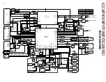
KDC-MPV619/MPV7019/MPV7020/MV6521

8

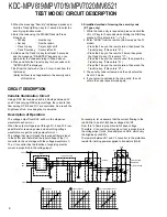
TEST MODE / CIRCUIT DESCRIPTION

The voltage output from DAC will be in the step-wise
waveform as shown in 

A

.

When the output voltage is put through R1-3 and C1-3 low-
pass filters for removing noise and smoothing voltage
waveforms, we get the voltage waveform of 

B

.

The voltage that went through the low-pass filters is input
to the buffer and that will be the input voltage of the V-I
converter in the next stage with the voltage waveform of 

C

.

The V-I converter has the function of supplying electric
current in proportion to the voltage input.

For example, let us assume that the current flowing in the
red LED is I

R

, and I

R

=(Q4 base voltage-V

BE

)/R7.

From this, I

R

flows in proportion to Q4 base voltage.

Therefore, V-I converter will supply current in proportion to
the voltage input to red, blue and green LED's, which vary
the brightness of LED's.
The resistor between D1 and V-I converter is the protection
resistor for limiting power supplied to transistors (Q4-6).

Using a DAC that can be varied in 256 steps between 0V
and 5V and varying DAC output voltage, the currents that
flow among R7, R9 and R11 are controlled. As a result, the
brightness of red, blue and green is adjusted.

Description of Operation

Variable Illumination Circuit

3. When the message "Security" is displayed, press and

hold the Track Up/Down key for 1 second to enter the
security registration mode.

4. Enter the code using the FM/AM/Track Up/Track

Down keys.

• FM key

: Number up

• Am key

: Number down

• Track Up key

: Cursor right shift

• Track Down key

: Cursor left shift

5. Hold down the Track Up key for at least 3 seconds

and the message, "RE-ENTER" appears, so once
again enter the code according to Step 4 above.

6. Press and hold the Track Up key for 3 seconds until

"APPROVED" is displayed.

7. Exit from the test mode. (See 2. How to exit from the

test mode)
(Note) All Clear is not applicable to the security code

of this model.

3. Simplified method of clearing the security code 

(K Type only)
1. While the code entry is requested, press and hold the

VOL UP key for 3 seconds while holding the DISP key
pressed. (This should turn "----" off.)

2. Enter "KCAR" from the remote. (Same way as the 01

model)
• Press the 5 key on the remote twice, then press the

Track Up key. (This enters "K".)

• Press the 2 key on the remote 3 times, then press

the Track Up key. (This enters "C".)

• Press the 2 key on the remote once, then press the

Track Up key. (This enters "A".)

• Press the 7 key on the remote twice, then press the

Track Up key. (This enters "R".)

3. The security code is cleared and the unit enters the

ALL OFF mode.

4. If you commit a mistake in the code entry, the unit

enters the code request mode again.

CIRCUIT DESCRIPTION

www. xiaoyu163. com

QQ 376315150

9

9

2

8

9

4

2

9

8

TEL 13942296513

9

9

2

8

9

4

2

9

8

0

5

1

5

1

3

6

7

3

Q

Q

TEL  13942296513  QQ  376315150  892498299 

TEL  13942296513  QQ  376315150  892498299 

Содержание KDC-MV6521

Страница 1: ...y A64 2590 02 KDC MPV619 Front glass B10 4174 01 Panel assy A64 2596 02 KDC MPV7020 Front glass B10 4169 01 Panel assy A64 2591 02 KDC MPV7019 Front glass B10 4178 01 Panel assy A64 2600 02 KDC MV6521 CD RECEIVER KDC MPV619 MPV7019 KDC MPV7020 MV6521 SERVICE MANUAL This service manual does not include information on the CD mechanism assembly exploded view parts list schematic diagram or mechanism ...

Страница 2: ... Q43 Q7 8 IC4 Q5 6 Q1 4 IC3 DATA C CH CON DATA H REQ H RST CLK REQ C CD MECHA B SERVO B PLL DATA PLL CLK M STOP M RST SW4 MUTE R MUTE L LO EJ MOSW SW2 SW3 SW1 S METER IFC OUT SW5V 3 PANEL DET GUIDE ILL MP IN AFS LEVEL RDDA FM AM A 8V for MP3 BU5V A8V 3 2 2 3 10 7 3 SW5V 10 SDA SCL AUDIO OUT 7 A8V BACK UP 3 2 O CLK O DATA O CE REMO RESET BU5V MUTE DRIVER PANEL5V PANEL5V RGB CONTROL 3 2 5 CD AM B FM...

Страница 3: ...081 V I converter Current driver for red LED Q62 2SC4081 Buffer Control voltage buffer for red LEDs brightness Q63 2SC4081 Buffer Control voltage buffer for green LEDs brightness Q64 2SC4081 Buffer Control voltage buffer for blue LEDs brightness UPD703030GFA03 IC1 or UPD703033GFA05 System MI COM or UPD703033GFA13 IC2 TDA7407D E VOL N C MPX IC IC3 HD74HC02FP Mute logic 2 input NOR x 4 or TC74HC02AF...

Страница 4: ...7 DTC114YUA or UN5214 P CON SW When Q27 s base goes Hi Q32 is turned on Q32 2SB1277 Q R or 2SB1434 Works during POWER ON mode Q29 DTA124EUA or KRA303 P CON protection inhibit SW Prevents Q30 tuning ON during start up after power ON Q30 2SA1576A or 2SB1218A P CON protection SW Protect Q32 by turning ON when P CON output is grounded Q28 DTC114YUA or UN5214 P ANT SW When Q28 s base goes Hi Q31 is tur...

Страница 5: ...del POWER OFF mode TEL MUTE on 24 P STBY O Power IC STBY control output Hi Power IC on ALL OFF mode Lo Power IC off 25 MUTE O Mute control output Lo Mute off Open Mute on 26 SW5V I O SW5V control terminal Lo SW5V on Hi Z SW5V off 27 BU DET I Momentary power down detection input Hi When momentary power down detected or BU OFF Lo BU ON 28 ACC DET I ACC detection terminal Hi ACC OFF Lo ACC ON 29 N C ...

Страница 6: ...n control terminal Lights on at the panel tilted during POWER ON mode Flashing at the panel detached during POWER ON mode 73 AVCONT O A D converter reference voltage control output Hi Active Connected to AVREF terminal 74 AVDD Positive power supply connection terminal Connected to BU 5V lines 75 AVSS Ground connection terminal Connected to GND lines 76 AVREF I A D converter reference voltage input...

Страница 7: ...ys Balance is adjusted in 3 steps of Left Max Center Right Max with the Track Up Down keys Fader is adjusted in 3 steps of Rear Max Center Front Max with the Track Up Down keys 8 Menu related specifications A short press of the MENU key initiates the Menu mode Pressing the DNPP SBF key on the remote initiates the Menu mode Continuous holding of a remote control key is inhibited 9 Backup current me...

Страница 8: ...e controlled As a result the brightness of red blue and green is adjusted Description of Operation Variable Illumination Circuit 3 When the message Security is displayed press and hold the Track Up Down key for 1 second to enter the security registration mode 4 Enter the code using the FM AM Track Up Track Down keys FM key Number up Am key Number down Track Up key Cursor right shift Track Down key...

Страница 9: ...9 16 1 9 6 1 E B B E B E 24 2 23 1 18 17 2 1 11 10 12 6 8 7 4 12 3 1 24 IC5 IC9 D120 IC2 IC7 D102 Q16 Q14 Q13 Q17 Q53 Q3 Q4 Q1 Q8 Q10 Q9 Q42 Q2 IC8 D114 IC10 IC11 IC6 IC1 D103 D104 D105 D106 D107 D108 D101 X25 9190 XX 9202 70 J74 1322 12 1387 12 CN4 D18 Q15 Q12 Q18 S1 J1 CN2 D1 CN3 D38 D34 D71 D39 D33 D30 D14 D32 Q32 D44 D42 D41 D45 D46 D47 D6 D2 D4 D5 D17 D12 IC4 WH1 D16 J2 A1 D31 D115 D13 Q47 D1...

Страница 10: ...0 Q22 Q26 Q19 Q45 Q46 Q51 Q43 Q33 Q34 D37 Q6 Q5 Q28 D112 D111 D110 D109 D116 X25 9190 XX 9202 70 J74 1322 12 1387 12 B E EB EB E B E B E B E B E B E B B E B E EB E B E B E B B E B E B E B E B E C53 C50 C57 C54 R21 R19 R20 R17 R18 C66 C67 1 C65 C6 C7 R54 R55 R56 R50 R28 R51 R53 R52 R63 R62 R64 R66 R65 R58 R57 R59 R61 R60 R15 R7 R16 R12 R9 R8 R11 R10 R1 R23 R27 R24 R2 R5 R6 R3 R4 C63 C64 C61 C62 C80...

Страница 11: ...216 100K R217 100k R218 100K R219 100k 2 2K R220 R221 100K R222 100K R223 100K C208 1000P R238 100K R233 1K R237 470 R235 47K R130 100K R236 100K R232 2 2K R231 2 2K R228 1k R129 100K R230 100K R205 100K 2 2k 2 2K R196 470 R197 470 R198 470 R199 1K R61 10K R88 24K R87 10K R89 3 3K 1 2W R93 1K 1 2W R80 22K R81 1K 1 2W R79 0 01 C78 22K R91 100K R94 22K R90 0 1u50 C74 10K R78 W108 0 01 C71 1u50 C73 R...

Страница 12: ...3 24 IF1 GND IF1 B SCL 15 16 18 19 20 17 DIG GND VDD 5V OSC GND OSC GND OSC GND OSC GND 3 7 11 13 8 Rch 2 D GND RST R124 4 7K 1K 0 01 R122 4 7K R25 4 7 R24 10 R121 100 R123 4 7K REQ H GND Rch A GND MUTE CH CON 10 9 11 13 12 B U 4 3 5 6 A GND MUTE CHCON 6 2 BU 7 8 3 4 9 10 REQ C DATA C CLK Lch DATA H 4 1 5 2 6 5 1 RF GND R23 10 R125 4 7K R126 4 7K R127 100 R128 100 REQ C CLK Lch DATA H DATA C 8 W N...

Страница 13: ...5 2 S20 1 S19 SRC S2 S10 AM FM S12 S14 S13 S11 S8 S16 S25 DISP Q3 1 2 to J1 IC1 LC75808W IC2 RS 171 Q1 6 DTA114EUA or Q3 4 2SD2114K Q4 Q5 Q6 B30 1599 05 D50 53 D26 with KEY MATRIX Q1 S27 RST VOL 3 S1 S4 S15 S7 Q5 50 64 B30 1605 05 D5 17 B30 1564 05 D80 81 D26 B LINE GND LINE KRA302 5V SW KEY ILLUMI RED SW AVR VLCD KEY PERMISSION SW M62333FP IC3 MA3082 L REMOTE SENSOR IC Q64 Q63 Q62 D50 D51 CONVERT...

Страница 14: ...8 46 N83 3012 46 N86 2606 46 X16 X89 J 1 FC1 701 740 741 781 734 780 708 758 782 759 223 225 257 226 228 231 236 237 202 213 256 RC1 RC2 277 276 278 200 DC1 DC2 207 790 795 X25 793 X25 794 X25 796 267 255 266 270 248 264 268 216 269 203 271 214 217 204 230 230 205 229 247 250 265 224 Ex2 242x2 222x2 A 1 X25 F1 249 227 PA1 235 DME1 242x2 242x2 D D E K E E J E K K K E E L L L E B A F H G G C C D D D...

Страница 15: ...s fournis Teile ohne Parts No werden nicht geliefert Ref No A d d N e w Parts No Description Dest inati on 200 1A A02 1486 13 PLASTIC CABINET ASSY 202 1B A52 0806 02 TOP PLATE 203 3A A21 4172 04 DRESSING PANEL SPRAY 204 3A A21 4174 03 DRESSING PANEL PLATING 205 3B A22 2932 02 SUB PANEL ASSY 207 2A A46 1754 01 REAR COVER PA1 3A A64 2590 02 PANEL ASSY K1 PA1 3A A64 2591 02 PANEL ASSY K2 PA1 3A A64 2...

Страница 16: ...00M ELECTRO 10UF 16WV K2ME C23 24 CE04NW1HR47M ELECTRO 0 47UF 50WV C25 CE04NW1A470M ELECTRO 47UF 10WV C27 30 CE04NW1C100M ELECTRO 10UF 16WV K2ME C33 CK73FB1H104K CHIP C 0 10UF K C34 CK73FB1H104K CHIP C 0 10UF K K1K2M C35 CK73FB1H104K CHIP C 0 10UF K K2ME C36 CE04NW1A470M ELECTRO 47UF 10WV M C41 CK73GB1A474K CHIP C 0 47UF K C42 CC73GCH1H151J CHIP C 150PF J C43 CK73GB1H333K CHIP C 0 033UF K C44 CK73...

Страница 17: ...R42 RK73GB2A103J CHIP R 10K J 1 10W Ref No A d d N e w Parts No Description Dest inati on R45 46 RK73GB2A472J CHIP R 4 7K J 1 10W K2ME R51 RK73GB2A101J CHIP R 100 J 1 10W R52 RK73FB2B223J CHIP R 22K J 1 8W R53 RK73GB2A222J CHIP R 2 2K J 1 10W R54 RK73GB2A223J CHIP R 22K J 1 10W R55 RK73FB2B103J CHIP R 10K J 1 8W R56 57 RK73FB2B102J CHIP R 1 0K J 1 8W R58 59 RD14DB2H2R2J SMALL RD 2 2 J 1 2W R60 RK7...

Страница 18: ...73GB2A153J CHIP R 15K J 1 10W R259 RK73GB2A104J CHIP R 100K J 1 10W K1M R260 RK73GB2A104J CHIP R 100K J 1 10W K2E R261 RK73GB2A104J CHIP R 100K J 1 10W K2M R262 RK73GB2A104J CHIP R 100K J 1 10W K1E R263 RK73GB2A104J CHIP R 100K J 1 10W E R264 RK73GB2A104J CHIP R 100K J 1 10W K1K2M R266 RK73GB2A104J CHIP R 100K J 1 10W R268 RK73GB2A104J CHIP R 100K J 1 10W R269 271 RK73GB2A101J CHIP R 100 J 1 10W E...

Страница 19: ...DIGITAL TRANSISTOR M Q11 2SC4081 TRANSISTOR Q11 2SD1819A TRANSISTOR K1K2M Q12 2SA2057 TRANSISTOR Q13 2SA1576A TRANSISTOR Q13 2SB1218A TRANSISTOR K1K2M Q14 2SC4081 TRANSISTOR Q14 2SD1819A TRANSISTOR K1K2M Q15 2SA2057 TRANSISTOR Q16 DTC124EUA DIGITAL TRANSISTOR Q16 UN5212 DIGITAL TRANSISTOR K1K2M Q17 DTA124EUA DIGITAL TRANSISTOR Q17 KRA303 DIGITAL TRANSISTOR K1K2M Q18 2SD2375 TRANSISTOR Q19 DTC124EU...

Страница 20: ...MPV7019 MPV7020 MV6521 25 MEMO www xiaoyu163 com QQ376315150 9 9 2 8 9 4 2 9 8 TEL 13942296513 9 9 2 8 9 4 2 9 8 0 5 1 5 1 3 6 7 3 Q Q TEL 13942296513 QQ 376315150 892498299 TEL 13942296513 QQ 376315150 892498299 ...

Страница 21: ...S N 50dB 15 2dBf 1 6µV 75Ω 15 2dBf 1 6µV 75Ω 15 2dBf 1 6µV 75Ω Frequency Response 3 0dB 30Hz 15kHz 30Hz 15kHz 30Hz 15kHz 30Hz 15kHz S N 70dB MONO 70dB MONO 70dB MONO 65dB MONO Selectivity DIN 80dB 400kHz Selectivity 80dB 400kHz 80dB 400kHz 80dB 400kHz Stereo Separation 40dB 1kHz 40dB 1kHz 40dB 1kHz 35dB 1kHz AM MW Frequency Range 530kHz 1700kHz 10kHz 530kHz 1700kHz 10kHz 531kHz 1611kHz 9kHz 531kHz...

Отзывы: