DV-4070-B/4900/DVF-R7030-B/R9030
16
ADJUSTMENT
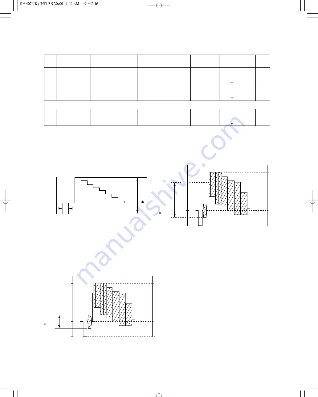
Fig. 3
No. ITEM
INPUT
SETTING
OUTPUT SETTING
ALIGNMENT
POINT
ALIGNMENT
FOR
FIG.
1
Y,Cb,Cr LEVEL
100% COLOR BAR DISC
Connect the oscilloscope to
Y output with 75-ohms
resistor
VR601
Y-signal =
1000mV
30mV
FIG.1
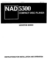
2
Y LEVEL
100% COLOR BAR DISC
Connect the oscilloscope to
COMPOSIT output with 75-
ohms resistor
VR600
COMPOSIT-signal =
1000mV
30mV
FIG.2
You need the step 1and 2 before next step 3
3
CHROM LEVEL
100% COLOR BAR DISC
Connect the oscilloscope to
COMPOSIT output with 75-
ohms resistor
VR602
Chrom-signal =
285mV
14mV
FIG.3
1000mV
30mV
Y
4.7 s
-2.86
0
714
(100IRE)
[mV]
white
yellow
cyan
green
magenta
red
blue
black
714
641
516
443
324
252
127
54
285mV
14mV
IRE’
Peak white
Blank
Sync. chip
0
-40
1000mV
30mV
IRE’
Peak white
Blank
Sync. chip
0
100
-40
Fig. 1
Fig. 2


