Kenwood DNX520VBT Скачать руководство пользователя страница 4

4


|


DNX520VBT

PRK SW

ILLUMI

1

2

3

4

5

6

7

8

1

2

3

4

5

6

7

8

Connection

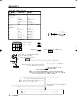
Connector Function Guide

Pin Numbers for 
ISO Connectors

Cable Colour

Functions

External Power 
Connector
A-4

Yellow

Battery

A-5

Blue/White

Power Control

A-6

Orange/White

Dimmer

A-7

Red

Ignition (ACC)

A-8

Black

Earth (Ground) Connection

Speaker 
Connector
B-1

Purple

Rear Right (+)

B-2

Purple/Black

Rear Right (–)

B-3

Gray

Front Right (+)

B-4

Gray/Black

Front Right (–)

B-5

White

Front Left (+)

B-6

White/Black

Front Left (–)

B-7

Green

Rear Left (+)

B-8

Green/Black

Rear Left (–)

Battery wire (Yellow)

Ignition wire (Red)

Connect either to the power control terminal when using the optional 

power amplifier, or to the antenna control terminal in the vehicle.

Power control/ Motor antenna control wire 
(Blue/White)

Dimmer control wire (Orange/White)

(Orange/White)

Antenna Cord

FM/AM antenna 
input (JASO)

If no connections are made, do not let the cable come out from the tab.

Connect to the terminal that is grounded when either 

the telephone rings or during conversation.

Mute control wire (Brown)

To connect the Kenwood navigation system, 
consult your navigation manual.

Parking sensor wire (Light Green)

Connect to the vehicle's parking brake 
detection switch harness.

For the sake of safety, be sure to connect the parking sensor. 

Steering remote control wire 
(Light Blue/Yellow) 

To steering remote

Reverse sensor wire (Purple/White)

Connect to vehicle's reverse lamp harness when 

using the optional rear view camera.
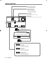
Connector A

Connector B

To use the steering wheel remote control feature, you need to an 
exclusive remote adapter (not supplied) matches your car is required.
When this terminal is not in use, leave its cap on. 

B54-4771-00̲00̲DNX520VBT̲E.indb   4

B54-4771-00̲00̲DNX520VBT̲E.indb   4

09.12.18   4:30:40 PM

09.12.18   4:30:40 PM

Содержание DNX520VBT

Страница 1: ... B54 4771 00 00 EW DNX520VBT GPS NAVIGATION SYSTEM INSTALLATION MANUAL ...

Страница 2: ...iring harness connector to the unit 7 Install the unit in your car 8 Reconnect the terminal of the battery 9 Press the reset button 2WARNING If you connect the ignition wire red and the battery wire yellow to the car chassis ground you may cause a short circuit that in turn may start a fire Always connect those wires to the power source running through the fuse box Acquiring GPS Signals The first ...

Страница 3: ... fit in the vehicle connector Insulate unconnected wires with vinyl tape or other similar material To prevent a short circuit do not remove the caps on the ends of the unconnected wires or the terminals If the console has a lid make sure to install the unit so that the faceplate will not hit the lid when closing and opening If the fuse blows first make sure the wires aren t touching to cause a sho...

Страница 4: ...control wire Blue White Dimmer control wire Orange White Orange White Antenna Cord FM AM antenna input JASO If no connections are made do not let the cable come out from the tab Connect to the terminal that is grounded when either the telephone rings or during conversation Mute control wire Brown To connect the Kenwood navigation system consult your navigation manual Parking sensor wire Light Gree...

Страница 5: ...English 5 ANT CONT P CONT MUTE REVERSE REMOTE CONT STEERINGWHEEL REMOTE INPUT Accessory 1 FUSE 15A GPS Antenna Accessory 3 see page 7 Bluetooth Microphone Accessory 2 see page 7 ...

Страница 6: ...t output White Audio right output Red Rear Preout Audio left output White Audio right output Red Subwoofer Preout Audio left output White Audio right output Red Rear View Camera input Visual input Yellow Audio Visual output Visual output Yellow Audio left output White Audio right output Red Visual input Resistance free mini plug 3 5φ Audio input Resistance free stereo type mini plug 3 5φ ...

Страница 7: ...signals might not be possible with an inside installation The GPS antenna should be installed at a position that is spaced at least 12 inch 30 cm from cellular phone or other transmitting antennas Signals from the GPS satellite may be interfered with by these types of communication Painting the GPS antenna with metallic paint may cause a drop in performance 1 Check the installation position of the...

Страница 8: ...8 DNX520VBT Installing the Navigation System Screws included in audio unit package ...

Страница 9: ......

Отзывы: