background image


                                                                        44/55                                                                            Rev. 1.1 

Item No. 

Photo 

Description 

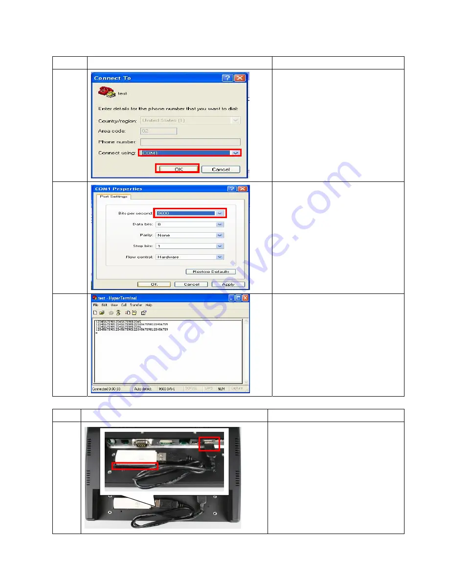
3.  Select on using COM3 port for 

barcode scanner (Select COM2 if 

MSR installed) 


4. Click 

“OK” 


1. Set Bits per second to be 9600 bps.   


1. Test OK 

2.3.4 WLAN  IEEE 

Item Photo 

Description 

1. Follow 2.1.1 item 1 to 11 


2.  Use adhesive tape to stick 

WLAN IEEE with rear cover 

3.  Plug in the WLAN IEEE cable to 

USB port 

4.  Follow steps back to 2.1.1 item 

5.  Follow the steps in driver CD for 

installation process 

Содержание MPOS50-8B-LX800

Страница 1: ...1 55 Rev 1 1 S Se er rv vi ic ce e M Ma an nu ua al l M MP PO OS S 5 50 0 S Se er ri ie es s M MP PO OS S5 50 0 8 8B B L LX X8 80 00 0 M Ma ar rc ch h 2 20 00 07 7...

Страница 2: ...r documentation even if advised of the possibility of such damages This document contains proprietary information protected by copyright All rights are reserved No part of this manual may be reproduce...

Страница 3: ...51 I O Board 27 2 1 10 LCD Rear Cover 28 2 1 11 I O Cover 28 2 1 12 MSR Module Base Power Button 28 2 1 13 MSR Reader Module Cover 29 2 1 14 52 I O Board 29 2 1 15 Battery Module 29 2 1 16 Handheld B...

Страница 4: ...Module 49 3 2 2 Battery Module Parts List Quotation 49 3 3 Recharge Cradle 50 3 3 1 Explode of Recharge Cradle 50 3 3 2 Recharge Cradle Part List Quotation 50 3 4 Accessories 54 3 4 1 Power Cord 54 3...

Страница 5: ...5 55 Rev 1 1 Chapter 1 CHAPTER Troubleshooting...

Страница 6: ...f fail RMA system to manufacturer 3100 NO POWER 1 Recharge cradle 2 Battery 3 Power button cable 4 52 I O board 5 M B to I O connector cable 6 MB 1 Check if main unit is well plugged or not The LED at...

Страница 7: ...inverter for testing 2 If fail check if LCD signal cable well connected on MB CN2 3 If yes to item 2 replace with another MB for testing 4 If fail replace with another LCD signal cable for testing 5...

Страница 8: ...rear cover open EMI chassis remove inverter cable on M B CN1 check if CF Card well connected with CF Slot 2 If yes to item 2 replace with another CF card for testing 3 If fail replace with MB for tes...

Страница 9: ...e 2 MSR 3 MB 1 Shut down power remove battery module check if MSR cable well connected with 52 I O Board 2 If yes to item 2 replace with another MSR for testing 3 If fail open rear cover open EMI chas...

Страница 10: ...ss Make a start up disk and copy BIOS and EXE file Item Photo Description 1 1 Put empty 1 44MB disk into USB floppy disk 2 Plug the disk into another computer with XP OS installed 3 Click My Computer...

Страница 11: ...tart up disk is created 6 1 Check the files in floppy disk 2 Leave 3 files in the floppy disk delete the rest files highlighted 7 1 Only 3 files left in the floppy disk COMMAND COM IO SYS hidden file...

Страница 12: ...on the screen Commend COM AWDFLASH EXE BIOS file Ex B010R 1 Bin Update BIOS file Item Photo Description 1 4 Reboot Mobile POS 50 5 Press Del button 6 Choose Advanced BIOS Features 7 Press Enter Key 2...

Страница 13: ...ed Ex awdflash b010wr10 bin 5 1 Press N Press Enter Key 6 1 Press Y Press Enter Key 7 Note DO NOT TURN OFF or RESET SYSTEM Until the BIOS update is completed Stopping the BIOS update before it is comp...

Страница 14: ...ss F1 to reset 9 1 Double check the BIOS version is updated when the system resets Note The BIOS contained here is exclusively for manufacturer MPOS 50 Series only manufacturer has no responsibility f...

Страница 15: ...15 55 Rev 1 1 CHAPTER Chapter 2 Disassembly Assembly...

Страница 16: ...mbly 2 1 Main Unit 2 1 1Touch Panel Touch Screen Holder Item Photo Description 1 1 Unpack handheld belt 2 1 Remove 2 screw pad 2 Remove 2 screws from I O cover 3 1 Move the clicker to right and push u...

Страница 17: ...ion 5 1 Remove 4 screws from MSR reader module cover 6 1 Remove MSR reader module cover 2 Remove handheld belt 7 1 Remove I O cover 8 1 Remove power button cable 2 Remove 4 screws from I O board 3 Rem...

Страница 18: ...1 Remove I O board from MSR module base 10 1 Remove 4 screws from MSR module base 11 1 Remove MSR module base 12 1 Remove 4 screws from LCD rear cover 2 Be aware of different screw length The misplace...

Страница 19: ...clicker 2 Push down the LCD rear cover to enable COM port go underneath the cover 3 Push up the LCD rear cover to loose clicker 14 1 Remove 2 hex nuts from COM port 2 Remove cable inverter to LCD 15...

Страница 20: ...Photo Description 16 1 Push up the EMI cover 17 1 Remove touch panel cable 2 Pull up the black tape 18 1 Remove the LCD module M B and EMI cover from touch panel module 19 1 Replace with another touc...

Страница 21: ...1 Follow 2 1 1 item 1 to 16 2 Remove cable touch panel to M B CN29 and pull up the black tape 3 Pull out LED cable from LED frames 4 Remove cables LCD to M B CN2 and LED to M B CN6 2 1 Remove 4 screw...

Страница 22: ...ove mylar from M B 5 1 Turn to front side Remove 4 screws from LCD chassis 6 1 Remove LCD cable 2 Replace with another LCD 2 1 3LCD Chassis Item Photo Description 1 1 Follow 2 1 2 item 1 to 4 2 Remove...

Страница 23: ...ve fan cable CN11 and switch cable CN13 3 Remove touch panel cable CN29 and pull up the black tape 4 Remove cable inverter to M B CN1 5 Remove LCD cable CN2 and LED cable CN6 6 Remove USB cable 2 and...

Страница 24: ...eplace with another M B 2 1 5EMI A D Cover 3 1 2 Item Photo Description 1 1 Follow 2 1 1 item 1 to 14 2 Remove 4 screws 3 Remove inverter cable 4 Remove 8 screws from speaker 2 1 Remove 2 screws from...

Страница 25: ...er 2 1 6Speaker Module Item Photo Description 1 1 Follow 2 1 1 item 1 to 14 2 Remove inverter cable 3 Remove 8 screws from speaker 4 Remove 4 screws 5 Open EMI cover 2 1 Remove audio cable CN17 from M...

Страница 26: ...m Photo Description 1 1 Follow item 2 1 1 item 1 to 14 2 Remove inverter cable 3 Remove 1 screw from inverter cover 1 Remove 2 screws from inverter cover 2 1 Remove 2 screws from inverter 3 4 1 Replac...

Страница 27: ...another inverter cover 2 1 9 51 I O Board Item Photo Description 1 1 Follow 2 1 1 item 1 to 14 2 Remove inverter cable 3 Remove 4 screws 4 Open EMI cover 2 1 Remove I O cable from EMI cover 3 2 3 1 Tu...

Страница 28: ...item 1 to 13 2 Replace with another LCD rear cover 2 1 11 I O Cover Item Photo Description 1 1 Follow 2 1 1 item 1 to 6 2 Replace with another I O Cover 2 1 12 MSR Module Base Power Button Item Photo...

Страница 29: ...emove MSR reader module cover 2 1 Replace with another MSR reader module cover 2 1 14 52 I O Board Item Photo Description 1 2 Follow 2 1 1 item 1 to 8 3 Replace with another 52 I O Board 2 1 15 Batter...

Страница 30: ...to Description 1 Unpack handheld belt 1 2 1 Remove 4 screws from MSR reader module cover 1 Replace with another handheld belt 3 2 2 Cables 2 2 1Cable M B to Inverter Item Photo Description 1 1 Follow...

Страница 31: ...oto Description 1 Remove inverter to M B cable CN1 2 3 1 Replace with another inverter cable 2 2 2Cable M B To LCD Item Photo Description 1 1 Follow 2 1 2 item 1 to 6 2 Remove LCD cable 1 1 Replace wi...

Страница 32: ...e M B To LED Item Photo Description 1 1 Follow 2 1 1 item 1 to 16 2 Pull out the 2 LED from LED frames 3 Cut plastic belt Green at the left white in the middle 4 Remove LED cable CN6 3 2 4 2 1 Replace...

Страница 33: ...le CN13 3 Remove touch panel cable CN29 and pull up the black tape 4 Remove inverter cable CN1 5 Remove LCD cable CN2 and LED cable CN6 6 Remove USB cable 2 and audio cable CN17 7 Remove COM 3 cable 8...

Страница 34: ...tem Photo Description 1 1 Take out MSR module 2 1 Follow 2 1 1 item 1 to 5 2 Put MSR module at upper position 3 Fasten 2 screws to tighten MSR module 4 Plug MSR cable to I O board 5 Follow steps back...

Страница 35: ...35 55 Rev 1 1 Item No Photo Description 2 1 Click Yes to continue 3 1 Set area code and click OK 4 1 Click OK 5 1 Enter a name and Click OK...

Страница 36: ...36 55 Rev 1 1 Item No Photo Description 1 Select on using COM2 port for MSR Select COM3 if scanner installed 6 2 Click OK 7 1 Set Bits per second to be 9600 bps 1 Test OK 8...

Страница 37: ...t card module 2 1 Follow 2 1 1 item 1 to 5 2 Remove MSR reader module cover 3 Turn MSR reader module cover to the other side 1 2 3 1 Put smart card in the reader module 2 Fasten 2 screws to tighten sm...

Страница 38: ...1 1 Verification Item Photo Description 1 1 Click start Setting Control Panel System 2 1 Click Hardware 2 Click Device Manager 3 1 Click Detect plug in device 2 Double click USB Device 4 1 Click Upda...

Страница 39: ...1 Item Photo Description 5 1 Click Yes this time only 2 Click Next 6 1 Click Install from a list or specific location 2 Click Next 7 1 Click Browse 8 1 Choose the location where the driver is stored...

Страница 40: ...40 55 Rev 1 1 Item Photo Description 9 1 Click Next 10 1 Click Finish and the installation process is completed 11 1 Click Shortcut to SYN_PcSc_Test 12 1 Click STD2000...

Страница 41: ...o smart card reader 14 1 The test result PASS will show on the screen 2 The installation is completed 2 3 3 Barcode Scanner Item Photo Description 1 1 Take out smart card module 2 1 Follow 2 1 1 item...

Страница 42: ...ghten barcode scanner 3 Turn Mobile POS 90 to the left 4 1 Put the cable into the connector on I O board 5 1 Push in the cable 2 Lock the cable by pushing in black clicker 3 Follow steps back to 2 1 1...

Страница 43: ...43 55 Rev 1 1 Item No Photo Description 2 1 Click Yes to continue 3 1 Set area code and click OK 4 1 Click OK 5 1 Enter a name and Click OK...

Страница 44: ...Click OK 7 1 Set Bits per second to be 9600 bps 8 1 Test OK 2 3 4WLAN IEEE Item Photo Description 1 1 Follow 2 1 1 item 1 to 11 2 Use adhesive tape to stick WLAN IEEE with rear cover 3 Plug in the WLA...

Страница 45: ...to USB port 4 Follow steps back to 2 1 1 item 1 1 Follow the steps in driver CD for installation process 2 3 6Compact Flash Item Photo Description 3 2 1 1 Follow 2 1 1 item 1 to 16 2 Put CF in the CF...

Страница 46: ...46 55 Rev 1 1 Chapter 3 CHAPTER Spare Parts...

Страница 47: ...uotation Item Part No Description Q ty Price USD Plastic Bezel 8 4 LCD W Water proof sealed stick 1 1 2 A10400237RH Touch Panel 8 4 Resistive HT 084F 5RA 002N 18 1 Call Sales 3 21100011RH AUO 8 4 LCD...

Страница 48: ...1 1 Item Part No Description Q ty Price USD 7 8 9 10 11 A10400561RH EMI Chassis Module 1 Call Sales 12 30200061BRH Cover 8 4 LCD rear cover Black 1 Call Sales 13 30200051BRH Cover I O Cover Black 1 C...

Страница 49: ...c Base Reader Module Base PC ABS Black 1 Call Sales 5 10100039RH 52 I O Board 1 Call Sales 10 30200057BRH 30500026RH Cover Reader Module Cover Black W Len LED 1 Call Sales 11 30200059BRH Cover Scanner...

Страница 50: ...55 Rev 1 1 3 3 Recharge Cradle 3 3 1Explode of Recharge Cradle 3 3 2Recharge Cradle Part List Quotation Item Part No Description Q ty Price USD 1 2 3 5 6 A10400116RH Recharge Cradle Module 1 Call Sal...

Страница 51: ...erter cable Call Sales 21600103RH I O CONNECTOR cable P 2 0 44Pin MOLEX P 1 25 4Pin MOLEX P 1 25 4Pin MOLEX P 1 25 15Pin MOLEX P 1 25 Call Sales 21600095RH LCD CABLE for AUO panel Call Sales 21600041R...

Страница 52: ...hoto Price USD 31400004RH Heat pad 23 23 2 mm Call Sales 31700001RH 31700002R H Hand Held Belt Call Sales 40200016RH Carton Inner Packing Carton 321 228 585 mm Call Sales 40200024RH Carton Outer Packi...

Страница 53: ...tion Photo Price USD 40800014RH EPE Sponge for Mobile POS Main Unit Left and Right Call Sales 40800023RH EPE Sponge for Mobile POS Recharge Cradle Left and Right Call Sales 31800001RH 31800002R H Leat...

Страница 54: ...CORD FOR UK Call Sales 20700002RH POWER CORD FOR EUR Call Sales 20700004RH POWER CORD FOR Australia Call Sales 3 4 2 Memory Part No Description Photo Price USD 20300005RH 400MHz DDR MODULE 128M 200PI...

Страница 55: ...all Sales 3 4 5Smart Card PART NO Description Price USD A10400198RH Smart Card Module for Mobile POS Call Sales 3 4 6Barcode Scanner PART NO Description Price USD A10400197RH Barcode Scanner Module La...

Отзывы: