The D40 level switch houses a S.P.D.T (Single Pole Double
Throw) switch. The standard switch is suitable for all general
control circuit applications up to 500V AC. It is ideal for the
control of pump starters, relay logic circuits, and for the
direct control of contactors and timers.
The standard switch
can operate at ANY voltage from 5 to 500VAC. It is rated to
directly control motors up to 1.5kW (2HP).
EARTHING THE D40
ELECTRICAL
KELCO
Engineering Pty Ltd
ABN
20 002 834 844
Head office and factory:
9/9 Powells Road Brookvale NSW 2100 Australia.
Postal Address:
PO Box 7485 Warringah Mall Post
Shop Brookvale NSW 2100 Australia.
Phone:
+61 2 9905 6425
Fax:
+61 2 9905 6420
Email:
Web:
www.Kelco.com.au
PLEASE NOTE
: Kelco Engineering Pty Ltd reserves the right to change the specifi cation of this product without notice. Kelco Engineering Pty Ltd accepts no liability for personal injury or economic loss
as a consequence of the use of this product. All rights reserved copyright Kelco Engineering Pty Ltd © 2018 The Kelco D40 Displacer Level Switch is protected by a 12 month return to base warranty. Full
details of our warranty can be downloaded from: http://www.kelco.com.au/warranty
An M4 earth screw is provided inside the lid of the D40 level
switch. In the interests of safety, all applications should be
properly earthed using the earth screw.
CABLE ANCHOR
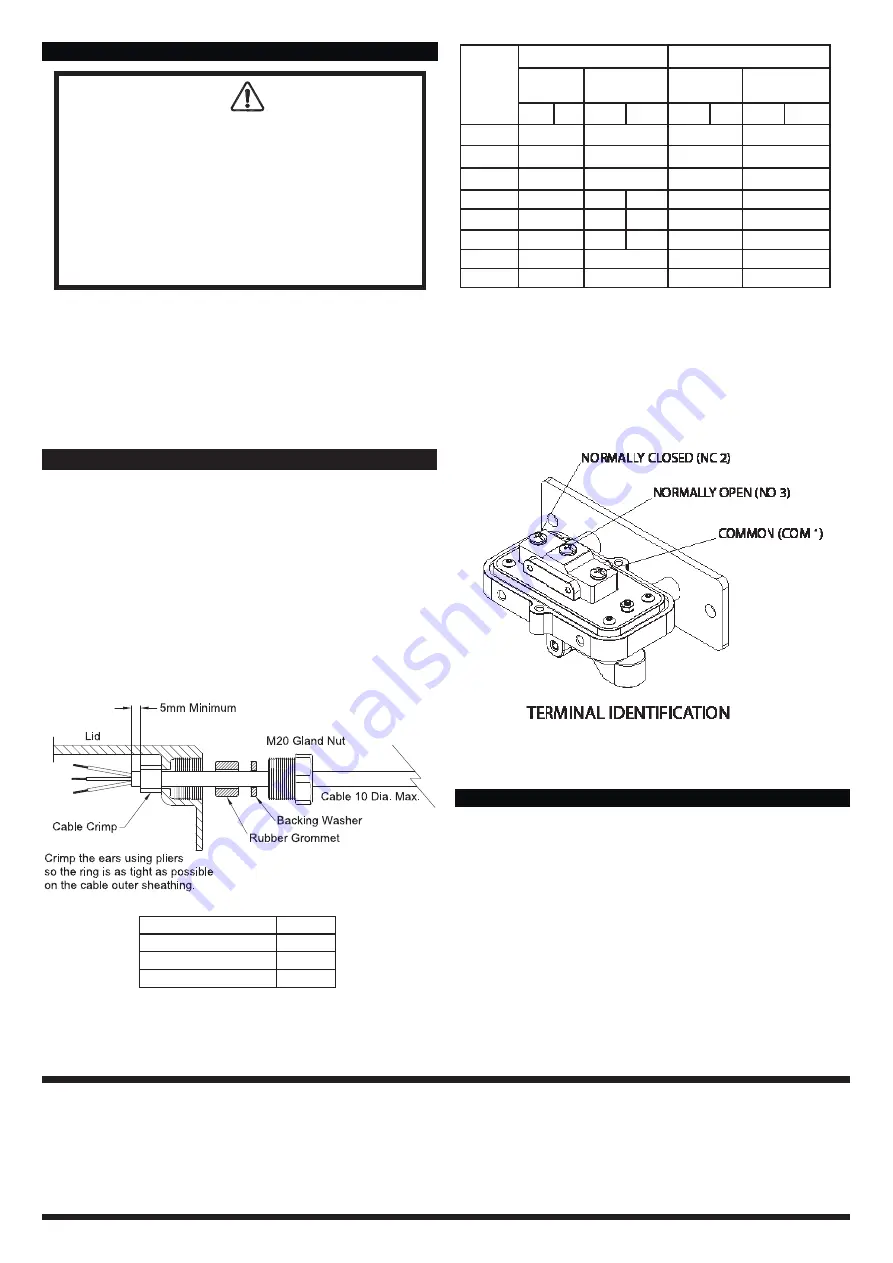
Each D40 level switch is shipped with two cable crimps to
suit various cable sizes. A cable crimp should be crimped
onto the outer sheathing of the cable at least 5mm back from
the end of the outer sheathing. The cable should then be
pulled back through the cable gland until the cable crimp
rests hard up against the inner wall of the cable gland. After
bedding the cable crimp into position, fully tighten the cable
gland.
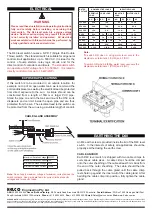
Note:
T
o switch ON when a rising water level covers the
displacer use terminals 1 (COM) and 3 (NO)
To switch ON when a falling water level uncovers the
displacer use terminals 1 (COM) and 2 (NC)
Note:
Do not apply maximum voltage at maximum current across the
switch contacts. See main data table for current limits at specifi c
voltages and for specifi c loads.
RATED
VOLTAGE
NON INDUCTIVE LOADS
INDUCTIVE LOADS
RESISTIVE
LOAD
LAMP LOAD
INDUCTIVE
LOAD
MOTOR LOAD
NO
NC
NO
NC
NO
NC
NO
NC
125 VAC
20 A
7.5 A
20 A
12.5 A
250 VAC
20 A
7.5 A
20 A
8.3 A
500 VAC
15 A
4 A
10 A
2 A
8 VDC
20 A
3 A
1.5 A
20 A
12.5 A
14 VDC
20 A
3 A
1.5 A
15 A
12.5 A
30 VDC
6 A
3 A
1.5 A
5 A
5 A
125 VDC
0.5 A
0.5 A
0.05 A
0.05 A
250 VDC
0.25 A
0.25 A
0.03 A
0.05 A
WARNING
Please read these installation and operating instructions
fully and carefully before installing or servicing this
level switch. The D40 level switch is a mains voltage
device. Death or serious injury may result if this switch
is not correctly installed and operated. All electrical
work associated with this switch must be performed by
a fully qualifi ed and licenced electrician.
If this switch is to be mounted in an outside location, for
example on top of an open water tank, we recommend the
cord and displacers as well as the electrical lead be protected
from direct exposure to the sun. A simple shroud can be
constructed from a length of 50mm or larger PVC pipe.
Stand the pipe on end in the tank and mount the D50 so its
displacers and cord sit inside the open pipe and are thus
protected from the sun. The electrical lead to the switch can
be protected from the sun using a siutable length of conduit.
EXPOSED APPLICATIONS
CABLE GLAND ASSEMBLY
Maximum Switched Voltage 500VAC
Maximum Switched Current 15A
Minimum Switched Voltage
5VDC
Minimum Switched Current
160mA


