Chapter 4
42
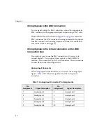
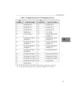
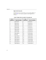
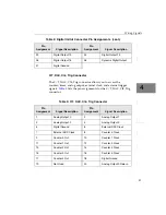
Connecting Digital I/O Signals
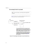
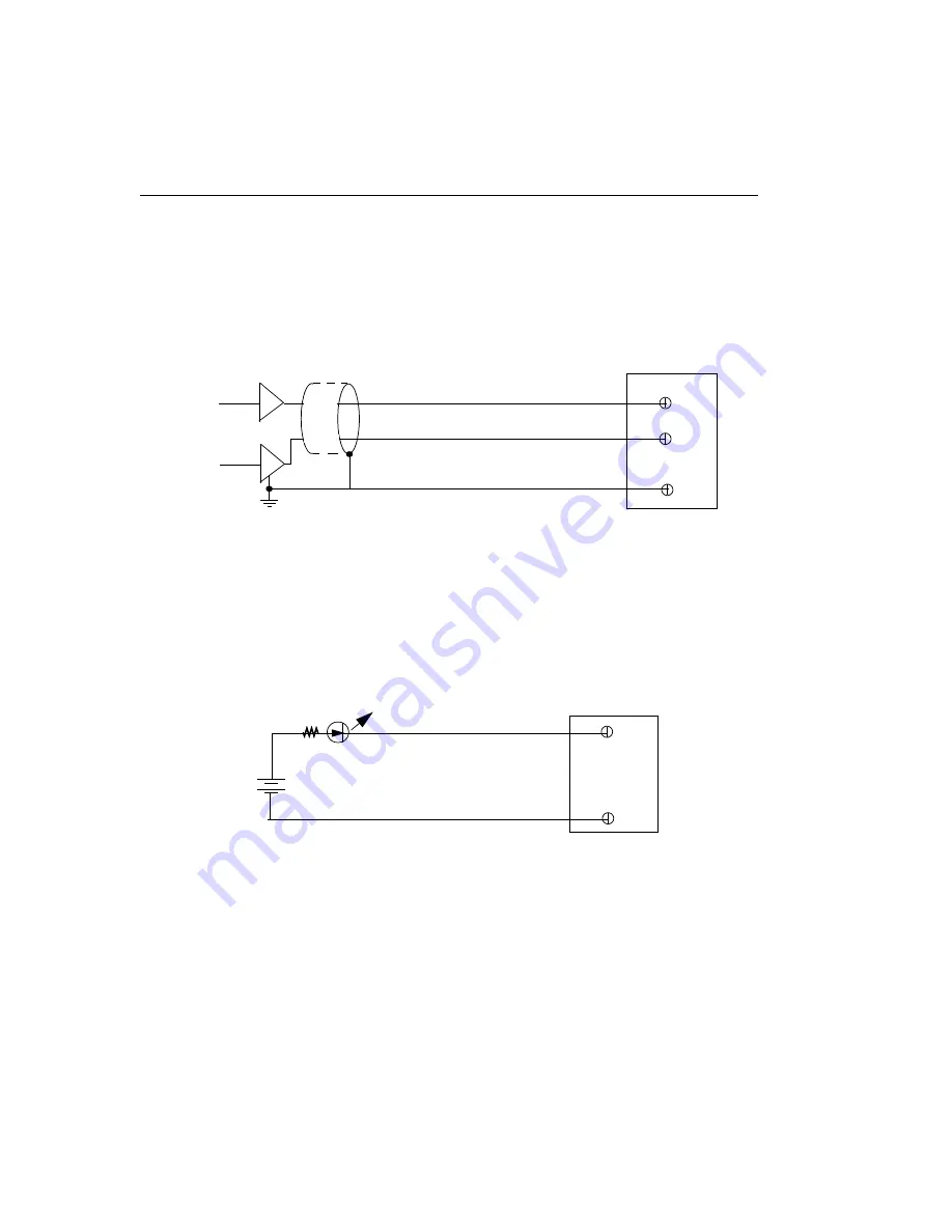
shows how to connect digital input signals (lines 0 and 1, in
this case) to your own screw terminal panel.
Figure 16: Connecting Digital Inputs to a Screw Terminal Panel
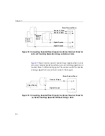
shows how to connect a digital output (line 0, in this case)
to your own screw terminal panel.
Figure 17: Connecting Digital Outputs to a Screw Terminal Panel
Digital Input 0
1
Digital Input 1
Digital Ground
TTL Inputs
2
Screw Terminal Panel
17
Digital Out 0
Digital Ground
-
+
500
Ω
5 V
0 Out = LED On
20
37
Screw Terminal Panel
Содержание KUSB-3116
Страница 10: ...Contents x...
Страница 14: ...About this Manual xiv...
Страница 15: ...1 1 Overview Hardware Features 2 Supported Software 4 Getting Started Procedure 5...
Страница 20: ...Chapter 1 6...
Страница 21: ...7 2 Preparing to Use a Module Unpacking 9 Checking the System Requirements 10 Installing the Software 11...
Страница 26: ...Chapter 2 12...
Страница 64: ...Chapter 4 50...
Страница 65: ...51 5 Verifying the Operation of a Module Overview 53 Running the Quick Data Acq Application 54...
Страница 75: ...61 A Ground Power and Isolation Connections...
Страница 78: ...Appendix A 64...
Страница 82: ...Index 68...

