Section 3: Functions and features
Model DMM7510 7½ Digit Graphical Sampling Multimeter Reference Manual
3-104
DMM7510-901-01 Rev. B / May 2015
Run the test:
1. Press the
HOME
key.
2. Use 4-wire connections to connect the first resistor to the instrument.
3. Verify that the instrument is set to Continuous Measurement. If necessary, hold the
TRIGGER
key for 2 s and select
Continuous Measurement
.
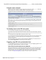
4. Observe the measurements. If the resistor is inside the limits set for Limit 1, L1PASS is displayed.
If the resistor is not within the limits, L1FAIL is displayed. If the resistor is in the limits set for
Limit 2, L2PASS is displayed. If the resistor is not within the limits, L2FAIL is displayed. An
example of a test that passed the L1 test but failed the L2 test is shown below.
Figure 132: Limit test pass and fail indicators
TSP-Link System Expansion Interface
Keithley Instruments TSP-Link
®
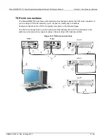
is a high-speed trigger synchronization and communication bus that
test system builders can use to connect multiple instruments in a master and subordinate
configuration. Once connected, all the instruments that are equipped with TSP-Link in a system can
be programmed and operated under the control of the master instrument or instruments. This allows
the instruments to run tests more quickly because they can be decoupled from frequent computer
interaction. The test system can have multiple master and subordinate groups, which can be used to
handle multi-device testing in parallel. Combining TSP-Link with a flexible programmable trigger
model ensures speed.
Using TSP-Link, multiple instruments are connected and can be used as if they are part of the same
physical unit for simultaneous multi-channel testing. The test system can be expanded to include up
to 32 TSP-Link-enabled instruments.
TSP-Link functionality is only available when using the instrument front panel or the TSP commands
to control the instrument. It is not available if you are using SCPI commands.


