Keithley 7999-6 Скачать руководство пользователя страница 50

Operation

3-23

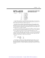
The Service Request Enable Register is shown in Figure 3-9. Notice that the decimal weight 

of each bit is included in the illustration. The sum of the decimal weights of the bits that you 
wish to set is the value that is sent with the *SRE command. For example, to set the ESB and 
MAV bits of the Service Request Enable Register, send the following command:

where:

ESB (bit B5) 

32

MAV (bit B4)

= __16 

<NRf> =

48

The contents of the Service Request Enable Register can be read using the *SRE? query 

command.

Figure 3-9
Service request enable register

Event:

ESB = Event Summary Bit

MAV = Message Available Bit

EAV = Error Available

MSB = Measurement Summary Bit

32

(2

5

)

16

(2

4

)

4

(2

2

)

ESB MAV

EAV

Bit position

Event

Decimal Weighting

B7

B5

B4

B3

B2

B1

B0

B6

Value

0/1

0/1

0/1

Value:  1 = Enable Service Request Event

0 = Disable (Mask) Service Request Event

Artisan Technology Group - Quality Instrumentation ... Guaranteed | (888) 88-SOURCE | www.artisantg.com

Содержание 7999-6

Страница 1: ...service in house repair center WE BUY USED EQUIPMENT Sell your excess underutilized and idle used equipment We also offer credit for buy backs and trade ins www artisantg com WeBuyEquipment REMOTE IN...

Страница 2: ...Model 7999 6GPIB RF Relay Unit Instruction Manual A G R E A T E R M E A S U R E O F C O N F I D E N C E Artisan Technology Group Quality Instrumentation Guaranteed 888 88 SOURCE www artisantg com...

Страница 3: ...ECT INDIRECT SPECIAL INCIDENTAL OR CONSEQUENTIAL DAMAGES ARISING OUT OF THE USE OF ITS INSTRUMENTS AND SOFTWARE EVEN IF KEITHLEY INSTRUMENTS INC HAS BEEN ADVISED IN ADVANCE OF THE POSSIBILITY OF SUCH...

Страница 4: ...ction Manual 2001 Keithley Instruments Inc All rights reserved Cleveland Ohio U S A First Printing April 2001 Document Number 7999 6 901 01 Rev A Artisan Technology Group Quality Instrumentation Guara...

Страница 5: ...enda are numbered sequentially When a new Revision is created allAddenda associated with the previous Revision of the manual are incorporated into the new Revision of the manual Each new Revision incl...

Страница 6: ...ains voltage or to voltage sources with high transient over voltages Installa tion Category II connections require protection for high transient over voltages often associated with lo cal AC mains con...

Страница 7: ...ffect of normal and common mode voltages Use standard safety precautions to avoid personal contact with these voltages The WARNING heading in a manual explains dangers that might result in personal in...

Страница 8: ...path up to 10 million counts each maintained in non volatile memory MAXIMUM COMMON MODE 42V peak any terminal to earth MAXIMUM SWITCHING SIGNAL 1W CW CAT I POWER User supplied 24VDC 22VDC min 30VDC ma...

Страница 9: ...Artisan Technology Group Quality Instrumentation Guaranteed 888 88 SOURCE www artisantg com...

Страница 10: ...s 2 2 Configuration 2 2 Layout 2 2 Simplified schematic 2 4 Connections 2 5 GPIB control connection 2 5 Power connector 2 8 3 Operation Introduction 3 2 Maximum signal considerations 3 2 Bus operation...

Страница 11: ...duction 4 2 Handling and cleaning precautions 4 2 Handling precautions 4 2 Card and connector cleaning 4 2 Performance verification 4 3 Environmental conditions 4 3 Recommended equipment 4 3 Channel r...

Страница 12: ...vent status 3 10 Figure 3 5 Status byte and service request SRQ 3 13 Figure 3 6 16 bit status register 3 17 Figure 3 7 Standard event enable register 3 20 Figure 3 8 Standard event status register 3 2...

Страница 13: ...Artisan Technology Group Quality Instrumentation Guaranteed 888 88 SOURCE www artisantg com...

Страница 14: ...E 488 2 common commands and queries 3 18 Table 3 5 ROUTe subsystem command set 3 27 Table 3 6 STATus subsystem command set 3 30 Table 3 7 SYSTem subsystem command set 3 32 Table 3 8 Error and status m...

Страница 15: ...Artisan Technology Group Quality Instrumentation Guaranteed 888 88 SOURCE www artisantg com...

Страница 16: ...1 GeneralInformation Artisan Technology Group Quality Instrumentation Guaranteed 888 88 SOURCE www artisantg com...

Страница 17: ...d connectors insulated 24VDC power connections LED indicators for error power and relay status Operating range to 4GHz relay dependent Can be upgraded from 4 pole to 6 pole relays Warranty information...

Страница 18: ...ty Specifications Full Model 7999 6 specifications are included at the front of this manual Unpacking and inspection Inspection for damage The Model 7999 6 is packaged in a re sealable anti static bag...

Страница 19: ...return the Model 7999 6 for repair carefully pack the unit in its original packing carton or the equivalent and follow these instructions Call the Repair Department at 1 800 552 1115 for a Return Mate...

Страница 20: ...2 Connections Artisan Technology Group Quality Instrumentation Guaranteed 888 88 SOURCE www artisantg com...

Страница 21: ...amination can reduce isolation resistance To avoid possible contamination Always grasp the switch by the handles or the relay housing Do not touch bulkhead connector insulators Operate the switch in a...

Страница 22: ...5 6 3 P W R E R R 1 4 2 5 6 3 1 7 9 9 9 6 G P IB R F R E L A Y U N IT R E L A Y 1 P W R E R R 1 4 2 5 6 3 1 4 2 5 6 3 R E L A Y 2 R E L A Y 1 Power LED ERR LED Relay 2 state LEDs Relay 1 state LEDs O...

Страница 23: ...relay Figure 2 3 Simplified schematic Power connector GPIB connector MS CODE 00313 RELAY 1 RELAY 2 INPUT POWER 24 VDC CATI WARNING NO INTERNAL OPERATOR SERVICABLE PARTS SERVICE BY QUALIFIED PERSONNEL...

Страница 24: ...tors may be stacked to allow a number of parallel connections to one instrument Two screws located on a standard connector maintain secure connections between connectors NOTE To minimize interference...

Страница 25: ...agement 11 ATN Management 12 SHIELD Ground 13 DI05 Data 14 DI06 Data 15 DI07 Data 16 DI08 Data 17 REN 24 Management 18 Gnd 6 Ground 19 Gnd 7 Ground 20 Gnd 8 Ground 21 Gnd 9 Ground 22 Gnd 10 Ground 23...

Страница 26: ...board there are five GPIB address DIP switches When shipped from the factory the GPIB address is set to 3 To change the GPIB address of the relay refer to Section 4 of this manual 1 12 13 24 Artisan T...

Страница 27: ...to prevent the risk of electric shock use only a properly rated power supply The power supply must be double insulated have the required safety agency approvals for the low voltage directives EMC dir...

Страница 28: ...3 Operation Artisan Technology Group Quality Instrumentation Guaranteed 888 88 SOURCE www artisantg com...

Страница 29: ...ands on page 3 26 Manual operation on page 3 34 Switching considerations on page 3 35 Errors on page 3 37 Maximum signal considerations WARNING Maximum voltage between any conductor and ground is 42V...

Страница 30: ...GPIB address DIP switches When shipped from the factory the GPIB address is set to 3 To change the GPIB address of the relay refer to Section 4 of this manual Programming syntax Syntax rules for prog...

Страница 31: ...the instrument Some programming operations require several command words Single Command Message This program message uses the command words required to perform a single programming operation Example S...

Страница 32: ...same command level see the ROUT CONF com mand word does not have to be repeated for the second command string Note also that the leading colon for CPOL2 is not used Common commands and SCPI commands...

Страница 33: ...the path from N type bulkhead con nector X201 to relay 1 output connector 5 see Figure 3 2 X 2 2 5 X 2 0 3 X 2 0 1 P W R E R R 1 4 2 5 6 3 1 4 2 5 6 3 R E L A Y 2 R E L A Y 1 O P E N A L L S T E P P...

Страница 34: ...se message After sending a query command the response message is placed in the output queue When the relay unit is then addressed to talk the response message is sent from the output queue to the comp...

Страница 35: ...receive the complete response message before another pro gram message can be sent to the relay unit Status model The relay unit provides status registers and queues allowing the operator to monitor a...

Страница 36: ...ters ESR ESE NRf ESE OPC 1 QYE DDE EXE CME 6 PON 8 9 10 11 12 13 14 15 OPC 1 QYE DDE EXE CME 6 PON 8 9 10 11 12 13 14 15 Operation Complete Query Error Device Specific Error Execution Error Command Er...

Страница 37: ...n turn sets the summary bit of the status byte register Figure 3 4 Standard event status PON B7 CME B5 EXE B4 DDE B3 QYE B2 B1 OR Standard Event Register Standard Event Enable Register PON Power On CM...

Страница 38: ...sets A data message is cleared from the output queue when it is read The output queue is considered cleared when it is empty A cleared output queue clears the MAV bit in the status byte register A mes...

Страница 39: ...rious forms for using the list parameter list 110 Single message 110 222 220 Comma separated entries When you enable messages messages not specified in the list are disabled When you dis able messages...

Страница 40: ...ry Messages B7 RQS B6 MSS ESB B5 MAV B4 EAV B2 B1 B0 OR SRE SRE Status Byte Register Service Request Enable Register MSS Master Summary Status RQS Request for Service ESB Event Summary Bit MAV Message...

Страница 41: ...bit in the status byte register When a summary bit of the status byte is set and its corresponding enable bit is set as programmed by the user the RQS MSS bit will set to indicate that an SRQ has occ...

Страница 42: ...program will simply proceed normally after the serial poll is performed If an SRQ does occur bit B6 of the status byte register will set and the program can branch to a service subroutine when the SRQ...

Страница 43: ...ueues Commands Description Ref To reset Standard event register ESE 0 or CLS Reset all bits of the Standard Event Register to 0 Note 1 To clear error queue CLS Clear all messages from error queue Note...

Страница 44: ...imal weights for the bits that you wish to set Note that Figure 3 6 includes the decimal weight for each register bit To set bits B5 B3 and B2 the parameter value would be the sum of the decimal weigh...

Страница 45: ...ard event enable register and clear it IDN Identification query Returns the manufacturer model number serial number and firmware revision levels of the unit OPC Operation complete command Set the oper...

Страница 46: ...R command A cleared bit 0 in the enabled register prevents masks the ESB bit in the Status Byte Reg ister from setting when the corresponding standard event occurs A set bit 1 in the enable reg ister...

Страница 47: ...ribed as follows Bit B0 Operation Complete A set bit indicates that all pending selected device operations are completed and the Model 7999 6 is ready to accept new commands This bit only sets in resp...

Страница 48: ...DN identification query Reads identification code The identification code includes the manufacturer model number serial number and firm ware revision levels Identification codes vary with the model nu...

Страница 49: ...lt column of SCPI tables and opens all relay paths 2 Cancels all pending commands 3 Cancels response to any previously received OPC and OPC commands SRE NRf Service Request Enable Program register SRE...

Страница 50: ...mmand where ESB bit B5 32 MAV bit B4 __16 NRf 48 The contents of the Service Request Enable Register can be read using the SRE query command Figure 3 9 Service request enable register Event ESB Event...

Страница 51: ...ows Bit 0 Not used Bit 1 Not used Bit 2 Error Available EAV A set bit indicates that an error or status message is present in the Error Queue The message can be read using one of the following SCPI co...

Страница 52: ...tuator is energized and that only the single path closed 3 The command places the coded result 0 or 1 in the output queue When the unit is addressed to talk the coded result is sent from the output qu...

Страница 53: ...all previous overlapped commands are finished The WAI command is not needed for sequential commands GPIB commands This section contains Model 7999 6 specific commands for the three different subsyste...

Страница 54: ...are closed Returns a clist of closed channels COUNt 1 clist Query the number of times the channel s for relay 1 have been closed Six comma separated values are returned corresponding to channels 1 6 C...

Страница 55: ...ding this query to a four pole relay still returns six values but for the four pole relay the values for channel 1 and 4 will always return a 0 To reset this count see CLOSe RCOunt 1 or CLOSe RCOunt2...

Страница 56: ...nds To send any of the following commands include the command path before the command For an example see description CPOLe 1 NRf Sets number of poles for relay 1 CPOLe 1 Query number of poles set on r...

Страница 57: ...all status registers to their default states send STAT PRES Query No query form of this command exists QUEue Path to queue commands This command path is required to access the following error queue co...

Страница 58: ...age 3 37 for a listing of error numbers and messages ENABle list Enable error queue messages ENABle Query for enabled error queue messages Parameter list numlist where numlist is a comma separated lis...

Страница 59: ...ssages from the error queue Description Use this command to clear all messages from the error queue For exam ple to clear all messages from the error queue send STAT QUE CLE Query No query form of thi...

Страница 60: ...the last memory location in the register On power up the error queue is empty If empty the message 0 No Error is placed in the error queue The messages in the error queue are preceded by a number Refe...

Страница 61: ...uence closes All channels on Relay 1 opened NOTE Switches control the state of the associated relay The switch located to the immediate left of Relay 1 controls the output relay while the switch to th...

Страница 62: ...nnectors can be damaged if they are not handled properly If connector insulation becomes contaminated the insulation resistance will be substantially reduced affecting high impedance measurement paths...

Страница 63: ...connectors PC board traces and relay Refer to the specifications located at the front of this manual for Model 7999 6 insertion loss information RFI EMI RFI Radio Frequency Interference and EMI Elect...

Страница 64: ...214 Trigger deadlock EE 213 Initialization ignored EE 212 Arm ignored EE 211 Trigger ignored EE 210 Trigger error EE 200 Execution error EE 171 Invalid expression EE 170 Expression error EE 161 Inval...

Страница 65: ...meter EE 108 Parameter not allowed EE 105 GET not allowed EE 104 Data type error EE 103 Invalid separator EE 102 Syntax error EE 101 Invalid character EE 100 Command error EE 000 No error SE 900 Inter...

Страница 66: ...4 ServiceInformation Artisan Technology Group Quality Instrumentation Guaranteed 888 88 SOURCE www artisantg com...

Страница 67: ...serve the following precautions when handling the switch Handle the Model 7999 6 only by the edges and cover Do not touch connector insulators Do not touch any board surfaces or components not associa...

Страница 68: ...uipment Table 4 1 summarizes the equipment necessary for performance verification channel resis tance tests Channel resistance tests Perform the following steps to verify the relay contact is closing...

Страница 69: ...thley Instruments Inc See the parts list in Section 5 for part numbers Model 2010 DMM 2010 MULTIMETER RANGE F 500V PEAK FRONT REAR 3A 250V AMPS HI LO INPUTS 350V PEAK 1000V PEAK SHIFT LOCAL POWER RANG...

Страница 70: ...l then blow dry the board with dry nitrogen gas After cleaning allow the card to dry in a 50 C low humidity environment for several hours before use Relay replacement Perform the following steps to di...

Страница 71: ...mbly 7999 6 100 Bulkhead Adapter Qty 6 SMA to N connector CS 1092 Front Panel 7999 6 302 Pan Head Screw Qty 8 8 32 x 1 2PPHNY Pan Head Screw Qty 4 6 32 x 5 16PPH Relay Enclosure 7999 6 301 Bottom Plat...

Страница 72: ...c contained in Figure 4 2 A cable should be attached to each of the six bulkhead adapters 8 Place the new relay on the bottom plate 7999 6 304 securing with four pan head screws 8 32 1 2 nylon washers...

Страница 73: ...RL 252 2 5 Remove the four kepnuts 6 32 located in the corners on the back of the front panel 7999 6 302 6 Separate the relay enclosure 7999 6 301 from the front panel 7999 6 302 7 Remove the flat hea...

Страница 74: ...screw 6 32 5 16 from the back of the relay enclosure 7999 6 301 This screw secures the digital board assembly 7999 6 100 to the relay enclosure 7999 6 301 8 Remove the power connector and GPIB connect...

Страница 75: ...4 10 Service Information Artisan Technology Group Quality Instrumentation Guaranteed 888 88 SOURCE www artisantg com...

Страница 76: ...5 ReplaceableParts Artisan Technology Group Quality Instrumentation Guaranteed 888 88 SOURCE www artisantg com...

Страница 77: ...al number Part description Component designation if applicable Keithley part number Factory service If the switch is to be returned to Keithley Instruments for repair perform the following Call the Re...

Страница 78: ...RAIGHT SOLDER PIN CS 368 16 J3 CONN RIGHT ANGLE 24 PIN CS 501 J5 CONN D SUB MALE BOARDLOCK TYPE CS 848 9 L1 FERRITE CHIP 600 OHM CH 62 L2 CHOKE CH 87 2 L3 INDUCTOR 82A CH 106 1 Q1 Q2 Q3 TRANS NPN TG 2...

Страница 79: ...IC 1026 U8 GPIB ADAPTER LSI 123 U9 IC OCTAL INTERFACE BUS IC 646 U10 IC OCTAL INTER BUS TRANS IC 647 U11 CMOS Static Ram LSI 162 70 U12 IC 512X 8 BIT CMOS WITH PROGRAM 7999 6 800 A01 U14 U16 U18 IC Q...

Страница 80: ...to front panel 6 32 5 16 Phillips Flat Head Screw 6 32X5 16PFH To mount bracket to enclosure 6 32 1 4 Phillips Pan Head Screw 6 32X1 4PPH To mount bracket to PCB Flat Head Screw 8 32 FA 323 2 To moun...

Страница 81: ...5 6 Replaceable Parts Artisan Technology Group Quality Instrumentation Guaranteed 888 88 SOURCE www artisantg com...

Страница 82: ...Artisan Technology Group Quality Instrumentation Guaranteed 888 88 SOURCE www artisantg com...

Страница 83: ...2 Connections 1 4 GPIB 2 5 introduction 2 2 SMA 2 8 Connector integrity 3 35 Controlling relay connections 3 6 E Electronic components 5 3 Enable registers 3 11 Environmental conditions 4 3 Error queu...

Страница 84: ...mber 5 2 Replacement parts 4 4 Replacement precautions 4 5 Replacing components 4 4 Response message terminator RMT 3 7 Response messages 3 7 RFI EMI 3 36 S Safety symbols and terms 1 3 Schematic 2 4...

Страница 85: ...ed input Calibration only Certificate of calibration required Data required attach any additional sheets as necessary Show a block diagram of your measurement including all instruments connected wheth...

Страница 86: ...Artisan Technology Group Quality Instrumentation Guaranteed 888 88 SOURCE www artisantg com...

Страница 87: ...Artisan Technology Group Quality Instrumentation Guaranteed 888 88 SOURCE www artisantg com...

Страница 88: ...84 93 07 40 Fax 089 84 93 07 34 GREAT BRITAIN Keithley Instruments Ltd The Minster 58 Portman Road Reading Berkshire RG30 1EA 0118 9 57 56 66 Fax 0118 9 59 64 69 INDIA Keithley Instruments GmbH Flat 2...

Страница 89: ...service in house repair center WE BUY USED EQUIPMENT Sell your excess underutilized and idle used equipment We also offer credit for buy backs and trade ins www artisantg com WeBuyEquipment REMOTE IN...

Отзывы: