background image

Содержание 1973

Страница 1: ...KEITHLEY Model1973 1972 IEEE 488 Interface Instruction Manual Contains Operating and Servicing Information Publication Date June 1991 Document Number 1973 901 01 Rev C...

Страница 2: ...RUMENTS INC NOR ANY OF ITS EMPLOYEES SHALL BE LIABLE FOR ANY DIRECT INDIRECT SPECIAL INCIDENTAL OR CONSEQUENTIAL DAMAGES ARISING OUT OFTHEUSEOFITSINSTRUMENTSANDSOFTWAREEVENIFKEHHLEYINSTRUMENTS INC HAS...

Страница 3: ...variable should always be used to read theserial poll byte regardless ofthe IEEE 488interfacecardorprogramminglanguage Thisisillustrated mtheexamplethatfollows Programming Example Routine to read the...

Страница 4: ...anual references to the Model197also refer to the Model197A references to the Models1973and 1972also refer to the Models1973A and 1972A respectively 1991 Keithley Instruments Inc All Rights Reserved I...

Страница 5: ...nds DCL SDC GET GTL UNT UNL SPE SPD Uniline Commands IFC REN EOI SRQ ATN Interface Functions SHl AHl T5 TEO L4 LEO SRI RLO PPO DCl DTI CO El Programmable Parameters Range REL dB EOI Trigger Calibra ti...

Страница 6: ...4 1 Uniline Commands 2 3 2 4 2 Universal Commands 2 3 2 4 3 Addressed Commands 2 4 2 4 4 Unaddressed Commands 2 4 2 4 5 Device Dependent Commands 2 4 2 5 Command Codes 2 4 2 6 Command Sequences 2 4 2...

Страница 7: ...ator Y 4 11 4 3 12 Buffer B 4 11 4 3 13 DigitalCalibrator V and Storage L 4 12 4 4 Talk Only Operation 4 12 SECTION 5 ANALOG OUTPUT Model 1972 only 5 1 Introduction 4 5 2 Using Analog Output 4 5 3 Out...

Страница 8: ...SECTION 8 REPLACEABLE PARTS 8 1 Introduction 8 1 8 2 Replaceable Parts 8 1 8 3 Ordering Information 8 1 8 4 Factory Service 8 1 8 5 SchematicDiagramsand ComponentLocation Drawings 8 1 III...

Страница 9: ...2 5 3 4 Interface Function Codes 2 6 3 5 IEEE Command Groups 2 6 4 1 GeneralBusCommands 2 4 2 Default Values StatusUponPowerUpor AfterSDCorDCL 4 3 4 3 Device DependentCommand Summary 4 5 4 4 Range Co...

Страница 10: ...7 Primary AddressSwitches Address20Shown 3 4 4 1 General Formatfor UO Command 4 8 4 2 Status Byte Format 4 10 4 3 Data Format 4 10 5 1 Analog OutputConnections 5 1 5 2 XIOOO Analog Output 5 2 6 1 Simp...

Страница 11: ...us TheprimaryaddressoftheModel197 1973maybeeas ilychangedbyusingthefiveaddressswitchesontherear paneloftheinstrument AllModel197operation issupported byIEEE program ming In addition numerousotherIEEEc...

Страница 12: ...lation and troubleshooting 5 Section6contains replaceable partsinformation 1 7 SPECIFICATIONS A completelistofIEEE specificationscan befound preced ing this section 1 8 UNPACKING AND INSPECTION The Mo...

Страница 13: ...same infor mation available simultaneously Exactly what is done with the information by each device depends on many factors in cluding device capabilties A typical bus configuration for controlled op...

Страница 14: ...line NDAC Not Data Accepted Theacceptor controls the state of the NDAC line The complete handshake sequencefor one data byte isshown in Figure 2 2 Once data is on the bus the source checks to see tha...

Страница 15: ...ote operation Generally the REN command should be sent before attempt ing to program the instruments over the bus EOI End Or Identify The EOI command is used to positively identify the last byte in a...

Страница 16: ...onding ASCII characters are listed in columns 4 A through 5 B The preceding address groups are combined together to form the Primary Command Group PCG The bus also has another group ofcommands called...

Страница 17: ...5 21 E 5 U 21 e u 0 1 1 6 ACK SYN 6 6 22 F 6 V 22 f V 1 7 BEL ETB 7 7 23 G 7 w 23 9 vs 0 8 BS GET CAN SPE 8 8 24 H 8 X 24 h x 9 HT TCT EM SPD 9 9 28 1 9 Y 25 V 10 LF SUB 10 26 J 10 z 26 z 1 11 VT ESC...

Страница 18: ...08 8 DCL 14 20 SPE 18 24 SPD 19 25 LAG 20 3F 32 63 TAG 40 5F 64 95 UNL 3F 63 UNT 5F 95 Values shown with 0 2 6 1 Addressed Command Sequence Before a device will respond to one of these commands it mu...

Страница 19: ...34 52 3 SDC Stays low EOT 04 4 4 Returns high Assumes primary address 20 Table 2 4 Typical Device Dependent Command Sequence Step Command ATIM State Data Bus ASCII Hex Decimal 1 UNL Set low 3F 63 2 L...

Страница 20: ...08 8 DCL 14 20 SPE 18 24 SPD 19 25 LAG 20 3F 32 63 TAG 40 5F 64 95 UNL 3F 63 UNT 5F 95 Values shown with 0 2 6 1 Addressed Command Sequence Before a device will respond to one of these commands it mu...

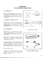
Страница 21: ...d connections Because of this flexibility system complexity can range from the very simple to ex tremely complex Figure 3 1 shows two typical system configurations Figure 3 l A shows the simplest poss...

Страница 22: ...ft unconnected to avoid ground loops Refer to Figure 3 5 to locate the connector on the rear panel of the Model 197 WARNING The voltage between IEEE common and chassis ground must not exceed 30V or da...

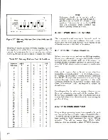
Страница 23: ...d from the factory with a primary address of20 10100 The primary address may be set to any value between0and 30aslong as address conflicts with other businstruments are avoided This may be done by pla...

Страница 24: ...lso true of the IEEE 488 bus which requires the use of handler routines as described in this section 3 3 1 Controller Interface Routines Before a controller can be used with the IEEE 488 interface the...

Страница 25: ...ess These are ordinary PCG Primary Command Group addresses sent by the HP 85 to facilitate bus operation in certain circumstances NOTE The HP 85 address is set to 21 at the factory Since each device o...

Страница 26: ...ties The Model1973 does not have extended talker capabilities LE Extended Listener Capabilities The Model 1973 does not have extended listener capabilities 3 3 4 Interface Commands Interface commands...

Страница 27: ...e commands All devices equipped to implement these commands will do so simultaneously when the command is sent General bus commands are summarized in Table 4 1 which also lists the HP 85 BASIC stateme...

Страница 28: ...o Local 4 2 5 SDC Selective Device Clear The GTL command is used to take the instrument out of the remote mode To send the GTL command the controller must perform the following sequence 1 Set ATN true...

Страница 29: ...ue when the talk address is transmitted and false when the status byte is read Programming Example The HP 85 SPOLL statement automatically performs the serial polling sequence To demonstrate serial po...

Страница 30: ...trument received the command No other changes occur with this example because no other commands were sent Programming Example Device dependent commands are sent by the HP 85 using the following statem...

Страница 31: ...tches to the correct range that corresponds to the range pushbutton selected Range control over the bus will be terminated Table 4 3 Device Dependent Command Summary Mode Command Description dB DO dB...

Страница 32: ...trument will be in the one shot on talk trigger mode The in strument is waiting for a trigger Trigger the instrument with a talk command by entering the following statement into the HP 85 ENTER 720 A...

Страница 33: ...e byte that is read with the SPE SPD command sequence and contains information on SRQ status and error and data conditions 4 The returned SRQ mode M value is determined by ad ding up the value of the...

Страница 34: ...then be displayed The Me bytes refer to Figure 4 1 contain 01 indicating that the Model 197is not programmed to SRQ on an IDDCO Status Byte Format The status byte contains informa tion relating to da...

Страница 35: ...I 80 NEXT I 90 DISP 100 DISP V V v 110 DISP SRQ ERROR IDDCO 120 DISP 130 END Set up for remote opera tion Program for SRQ on IDDCO Attempt to program illegal command op tion Perform serial poll Loop...

Страница 36: ...4 3 Data Format Model 197 is transmitted over the IEEE 488 bus as string of ASCII characters with the format shown in Figure 4 3 The firstfour characters indicate the function The mantissa of the rea...

Страница 37: ...terminator may be verified by entering the following statement into the HP 85 computer ENTER 720 A END LINE At this point the HP 85 ceases to operate because it is waiting for the standard CR LF term...

Страница 38: ...or exam ple Al Theinstrument willthen nm a display testand go into troubleshooting diagnostics Cycle power to re turn unitto normaloperation Revision A Software Cahbration constant storage over the IE...

Страница 39: ...essage Stor would have been displayed Revision B Software Storage ofcalibration constantsin NVRAM can only oc curifinstrumentcalibration isfirst enabled Iftheinstru mentis not placed in enable subsequ...

Страница 40: ...is displayed then calibration storage wasnot enabled and the calibration constants will only be valid imtil the Model 197is turned off NOTES 1 Onlyasmanysigruficantdigitsasnecessaryneed to be entered...

Страница 41: ...elected rate If r 6 is se lected presstheSTO CLRbuttoneverytimearead ingis desired 3 Turn off the data store by again pressing the STO CLR button TheSTO anmmciator turns off NOTE The instrument contin...

Страница 42: ...tput Connections The analog output is useful for monitoring the input signal with an external device such as a chart recorder Using the analog output connected to chart recorder produces a hard copy o...

Страница 43: ...Parameters V DCV ACV Input for 0 2 2V Input for 0 4V Range Range Analog Output Analog Output XI X1000 200mV 200mV 0 220mV 0 400 iV 2 V 2 V 0 2 2V 0 4mV 20 V 20 V 0 22V 0 40mV 200 V 200 V 0 220V 0 400...

Страница 44: ...splayed reading For example on the 200 000mV range a 2mV step in the analog output voltage corresponds to a0 2 tV change in applied voltage to the Model197 The extra resolu tion allows for a more cont...

Страница 45: ...diagram of the interface The 12 bit DAC U108 and the 4V Ref circuitry UlOlA B and C QlOl Q102 VRlOl U109 and associated circuitry is not present on the Model 1973 The following descriptions cover the...

Страница 46: ...To address the Model 197 the controller must send the primary address of the Model 197 The factory set address is 20 10100 The microprocessor reads the primary addressfrom SWlOl and then knows which...

Страница 47: ...1973 interface This isolation allows the Model 197 to maintain its 500V common mode floating specification The specification is maintained even if the interface is referenced to the IEEE controller gr...

Страница 48: ...e interface board loosely on the rear standoff WARNING Do not push down on J1008 The male con nector pins will pass through J1008 and may cause personal injury 5 Guide the terminals of P1008 into J100...

Страница 49: ...K HS 28 IEEE CONNECTOR CS 377 CONNECTOR HARDWARE CS 378 TO ADDRESSABLE SWITCHES SW 449 7 SW 449 8 1973A ANALOG OUTPUT JACKS 2 Required Not Shown 29316 Model 1972 only CONNECTOR CS 332 7 STANDOFF ST 17...

Страница 50: ...1972 for the XI gain 3 Apply l 1 9 XX V to the Model 197input 4 Measure the analog output voltage with the 4V2 digit DMM 5 Adjust R112 until the analog output reads within 0 0004V of the Model 197 di...

Страница 51: ...IPG command is sent Handshaking sequence refer to paragraph 2 3 2 Handshaking sequence refer to paragraph 2 3 2 Handshaking sequence refer to paragraph 2 3 2 5V 10 pulsed low at the end of multibyte t...

Страница 52: ...nnected to bus 5V Level when not connected to bus 4 i js OV 0 5V I 5V 10 pulsed low when an IPG command is sent Handshaking sequence refer to paragraph 2 3 2 Handshaking sequence refer to paragraph 2...

Страница 53: ...2 contains parts list information for the Model 1972 8 3 ORDERING INFORMATION To place an order or to obtain information concerning replacement parts contact your Keithley representative or the facto...

Страница 54: ...ion C5 E2 R 76 100k R105 Resistor 330Q 5 1 4W Composition C6 E2 R 76 330 R106 Resistor 330Q 5 1 4W Composition D5 F2 R 76 330 R107 Resistor 10k 5 1 4W Composition D5 F2 R 76 10k R108 Resistor 100k 5 1...

Страница 55: ...k 1 1 8W Metal Film Resistor 100k 5 1 4W Composition Resistor 330a 5 1 4W Composition Resistor 10k 5 1 4W Composition Resistor 100k 5 1 4W Composition Resistor 330S2 5 1 4W Composition Potentiometer 5...

Страница 56: ...r TIL117 E6 F2 IC 362 U114 GPIB Transceiver 75161 G3 D2 IC 299 U115 GPIB Transceiver 75160 G2 E2 IC 298 VR101 Diode Band gap reference 1 23V B5 C2 DZ 65 VR102 Diode Zener 5 1V A3 C3 DZ 59 VR103 Diode...

Страница 57: ...Unable to zero Unstable Will not read applied input Overload Calibration only C of C required Data required attach any additional sheets as necessary Show a block diagram of your measurement system in...

Отзывы: