background image


AAF, OAF, GSM, VMF 


Thermocouple Replacement 


Disconnect the furnace from the supply, and remove the furnace back panel. 


Make a note of the thermocouple connections.


The negative leg of the thermocouple is marked 

blue.


Compensating cable colour codings are: 


Negative 

positive (type K) 

 White 

green 


Disconnect the thermocouple from its terminal block. 


Bend the metal tag, or release the screw, to release the thermocouple sheath, withdraw the sheath, 
and shake out any fragments of thermocouple. 


Re-assemble with a new thermocouple observing the colour coding, ensuring that the 
thermocouple is not twisted as it is being inserted and that the metal tag is bent back, or the screw 
inserted, to grip the sheath. 

5.6 

Element Replacement  (AAF 11/3, AAF 11/7, GSM, OAF 11/1) 


See section 5.2 - wearing a face mask is recommended. 


The chamber of this type of furnace is formed by winding resistance heating wire on to a 
refractory muffle former. In the event of failure, the whole "wound muffle" assembly must be 
replaced. 


Disconnect the furnace from the supply and remove the furnace back panel. GSM: Pull the 
chimney out of the top of the furnace. 


Make a note of the wiring connections; see the section above which refers to the thermocouple 
colour coding. 


Unfasten the electrical connections to the inner chamber (brick-box) and remove the thermocouple 
and sheath (see thermocouple replacement instructions). If the connections are secured by 
hexagonal nuts, two spanners should be used to avoid cracking the porcelain mounting.  


Undo any self-tapping screws and hook bolts necessary to release the brick-box. 


Support the front of the brick-box as you withdraw it from the case so it does not fall onto the 
electrical connections below. 


Remove the brick-box lid and top insulating board, noting how it is assembled and observing the 
position of the heating element wires (or “tails”). 


Pull the element tails out of the terminal block and remove sufficient insulation to allow access to 
the heating element. Check and replace damaged insulation. 


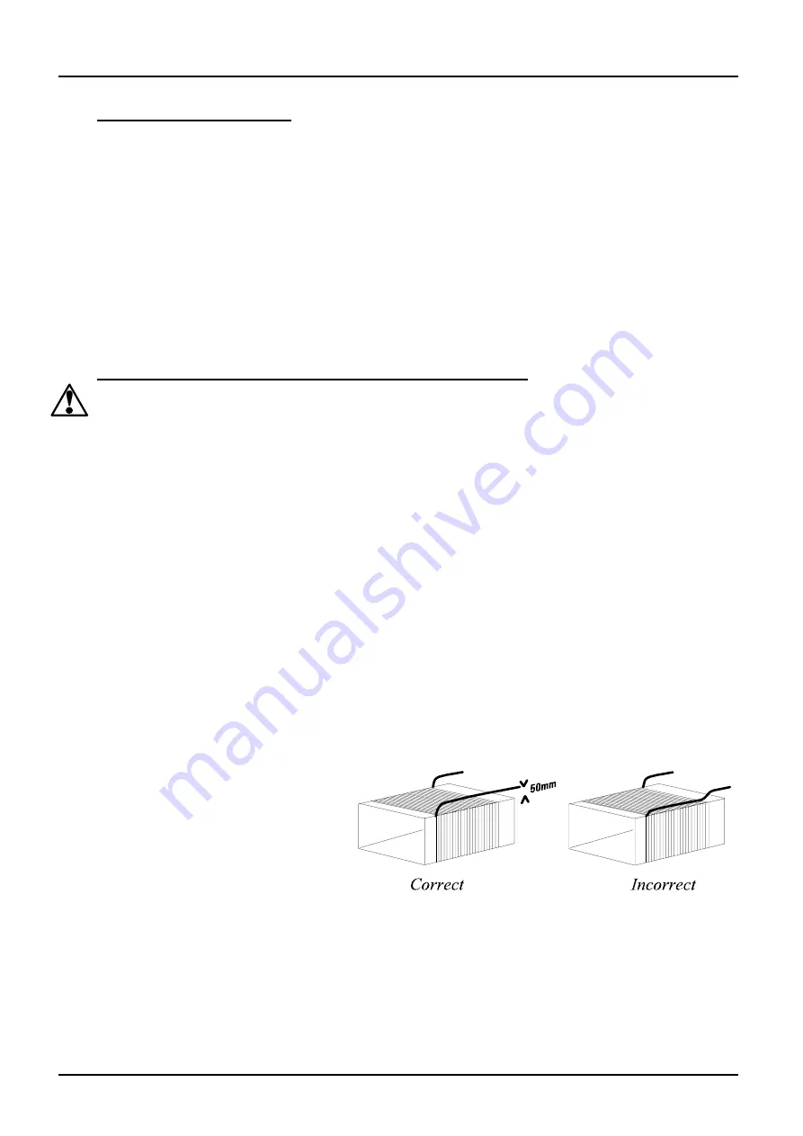
Fit the new heating element, 
ensuring that the tails are separated 
from the element by at least 25 mm 
(preferably 50mm) of insulation – 
see the picture. 


Feed the element tails through the 
terminal blocks and tighten the 
clamping screws using two spanners 
as before. Cut off excess element 
tails. 


Complete the fitting of the insulation and refit the lid. Do not use any cement unless supplied by 
Carbolite, as other types may chemically attack the heating element. 


Replace and fasten the brick-box into the furnace case. 

10 

MF06 

Содержание CARBOLITE AAF Series

Страница 1: ...d to the electricity supply CONTENTS Section page 1 0 Descriptions 2 2 0 Installation 3 3 0 Operation 4 4 0 Maintenance 7 5 0 Repairs Replacements 8 6 0 Fault Analysis 14 7 0 Circuit Diagrams 15 8 0 F...

Страница 2: ...r flow through the chamber 1 3 GSM 11 7 This is a conventional muffle furnace with a Silica chamber This gives a cleaner environment than a standard ceramic muffle 1 4 VMF 10 6 The Volatile Matter Fur...

Страница 3: ...models and AAF 11 7 may alternatively be ordered for use on two phases out of a 3 phase with neutral supply The model AAF 11 18 may also be ordered for 3 phase supply see section 2 4 Check the furnace...

Страница 4: ...perature controller see the controller manual OAF 11 2 the slave controller should be set to an offset temperature of zero see 3 2 Overtemperature option only If the overtemperature controller has not...

Страница 5: ...AAF OAF GSM VMF 3 3 MF06 5...

Страница 6: ...used to heat materials which emit smoke or fumes regularly heat it up to maximum temperature for one hour without load to burn away the soot Materials such as case hardening compounds and other react...

Страница 7: ...respondence please quote the serial number model type and voltage given on the rating label of the furnace The serial number and model type are also given on the front of this booklet when supplied wi...

Страница 8: ...Guidance Note EH46 We can provide further information on request Alternatively our service division can quote for any repairs to be carried out at your premises or ours 5 3 Temperature Controller Rep...

Страница 9: ...AAF OAF GSM VMF 5 5 MF06 9...

Страница 10: ...section above which refers to the thermocouple colour coding Unfasten the electrical connections to the inner chamber brick box and remove the thermocouple and sheath see thermocouple replacement ins...

Страница 11: ...ermocouple cables from their terminal blocks Straighten all the element tails Note that these become brittle with use Unscrew the screws fixing the metal back piece from the inner chamber and withdraw...

Страница 12: ...at the furnace is controlling properly to rule out the possibility that the previous element failed because of a fault elsewhere in the control circuit 5 9 VMF 10 6 Element Replacement See section 5 2...

Страница 13: ...s good emission of some fumes may be expected 5 11 Fuse Replacement Fuses are marked on the circuit diagram section 7 0 with type codes e g F1 F2 A list of the correct fuses is given in section 8 1 De...

Страница 14: ...o lights glowing on the controller The SUPPLY light is ON The controller may be faulty or not receiving a supply due to a faulty switch or a wiring fault The SUPPLY light is OFF Check the supply fuses...

Страница 15: ...d PE L N F2 F1 SSR F3 F3 safety switches A heat on e l e m e n t s for AAF 11 18 see diagram 7 4 7 2 OAF 11 2 single phase 7 3 Higher Voltages e g 254V For single phase models of 254V or above a contr...

Страница 16: ...AAF OAF GSM VMF 7 4 16 MF06...

Страница 17: ...n t s e l e m e n t s N L L N L N thermocouple Fuses or EMC filters Supply Terminals Circuit no 3 Circuit no 2 N L N L N L3 L2 L1 N PE L Circuit no 1 3 phase neutral A model made to this diagram can...

Страница 18: ...Customer fuses Required if no supply cable fitted Recommended if cable fitted See rating label for amperage see table below for fuse rating Model Phases Volts Supply Fuse rating AAF 11 3 1 phase 200 2...

Страница 19: ...l 41 41 541 5877 Fax 41 41 541 5878 Email General Information Sales info kesn ch Accounts Department accounts kesn ch USA O ce 233 Rogue River Highway 425 Grants Pass Oregon 97527 5429 USA Tel 1 503 2...

Отзывы: