11
5 Deburrer
5.1
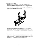
Assembling and mounting of deburrer
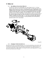
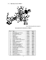
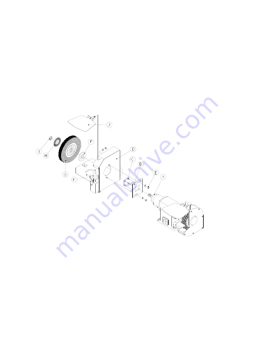
The deburrer cover is to be assembled in the order shown in
fig.: 5.1.
The four
screws in the end cover (A) must be unscrewed and the mounting plate (B) is to be
placed on the end cover (A), the four countersinked machine screws M6x20 (C) are
retightened. Now the deburrer cover (D) can be remounted through the two slashes
in the mounting plate (B). The cover can be repudiated back and forth so the steel
brush (G) can be used best possible. The inner flange (F) is put on the shaft with
the steel brush (G) and the outer flange (H). At last the reverse nut (I) is screwed on
the shaft and tightened. Before the lid on the deburrer cover (D) is closed the eye
shield is mounted (J) as shown in
fig.: 4.1
. If you are not to grind a pipe material
you can dismount the grinding system for pipe grinding (K) and the flat grinding
system beneath can be used instead.
Fig.: 5.1
5.2
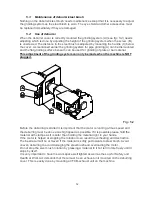
Changing of deburrer/steel brush
When the steel brush is worn approximately 10 % it must be replaced by a new brush. This
is easily done by opening the lid on the deburrer cover (D). Here you dismount the reverse
nut (I) and the flange (H) can be taken off with the steel brush. The new steel brush is
mounted in reverse order. Often it will be necessary to adjust the grinding system (K) before
the new steel brush is put in its place.
Содержание BO 50/5
Страница 18: ...17 7 4 PSD 5 belt arm Fig 7 4 Split drawing of PSD 5 belt arm...
Страница 20: ...19 7 5 VFCB exhaust system for PSD 5 Fig 7 5 Split drawing of VFCB exhaust system for PSD 5...
Страница 27: ...26 Disa Switch w emergency stop 8 4...
Страница 28: ...27 8 5 PSD 5 connected to EX16 Dust Extraction...


