background image

12

Safety

ServoOne User Manual SERCOS II and III

ID no.: 1108.26B.3-00     Date: 04/2020

Safety

2.3  General safety instructions and warnings

Hazards may emanate from our devices. For this reason pay attention to:


y

The safety instructions and warnings in this document!


y

Safety instructions and warnings in other documents, in particular the 

operation manuals related to the device product ranges!

Generally applicable safety instructions and warnings for the users of devices from  
KEBA Industrial Automation Germany GmbH : 

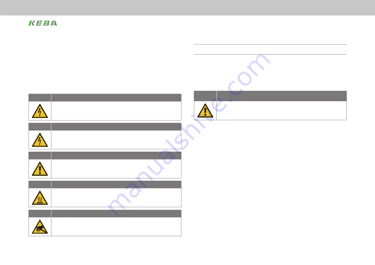
DANGER!

Risk of injury due to electrical power!


x

Carelessness will result in serious injuries or death.

Follow safety instructions and warnings in this document and on the device.

WARNING!

Risk of injury due to electrical power!


x

Carelessness may result in serious injuries or death.

Follow safety instructions and warnings in this document and on the device.

CAUTION!

Risk of injury or damage to the device due to incorrect operation!


x

Carelessness may result in minor injuries or damage.

Follow safety instructions and warnings in this document and on the device.

WARNING!

Risk of injury due to hot surfaces and components!


x

Carelessness may result in serious burns.

Electronic components may become hot during operation! 

Follow safety instructions and warnings in this document and on the device!

WARNING!

Risk of injury or damage due to electrostatic discharge!


x

Electrostatic discharge can destroy components and, in the worst case, cause injury 

or death. 

Do not touch electronic components and contacts!

Follow safety instructions and warnings in this document and on the device!

Pay attention to 

special safety instructions and warnings

 that are given here in the document before a specific 

action and that warn the user about a 

specific hazard

!

2.3.1 

Safety instructions related to this documentation 

The SERCOS automation bus is a communication system that is to be adapted at 
the boundaries of the drive systems ServoOne single-axis and multi-axis system and 
ServoOne junior to the situation in the installation. 

CAUTION!

The user may not be aware of changes to the parameters  

in the field bus system!


x

This situation can result in uncontrolled behaviour of the drive system!

Prior to system start, check parameters!

2.4  Important information

In the operation manuals for the drive product ranges you will find detailed information 
on the following areas:


y

Intended use.


y

Important instructions on the installation of your device.


y

Responsibilities of installers and organisations operating complete machines 

or installations.


y

Relevant laws, standards and directives applied.

Содержание ServoOne junior

Страница 1: ...ServoOne User Manual SERCOS II and SERCOS III ServoOne single axis system ServoOne multi axis system ServoOne junior ...

Страница 2: ...manual was compiled with the greatest care and attention based on the latest information available to us We should point out that this document will not always be updated simultaneously with the on going technical development of our devices Information and specifications may change For information on the latest version please visit www keba lti com In this documentation the functionality of the fo...

Страница 3: ...nfiguring basic settings 20 5 2 2 Setting the bus address on the slave 21 6 Parameter configuration 23 6 1 Profile parameter S 0 xxxx 23 6 1 1 Manufacturer specific parameters P xxxx 23 6 2 Structure of the SERCOS III parameters 23 6 2 1 Standard parameters S 0 xxxx x x 23 6 2 2 Manufacturer specific parameters P xxxx 24 Table of contents 1 General information 7 1 1 Target group 7 1 2 Prerequisite...

Страница 4: ...3 9 Functionality 55 9 1 Homing 55 9 1 1 Drive controlled homing command 55 9 1 2 SERCOS encoder 1 encoder 2 setting 55 6 3 Operation modes 24 6 3 1 Torque control 26 6 3 2 Speed control 27 6 3 3 Position control with drive controlled position profile generation 28 6 3 4 Position control without tracking error 30 6 3 5 External generation of the feed forward control signals 31 6 4 Real time bits 3...

Страница 5: ...ges and diagnostics 61 10 1 Standard parameters for error diagnostics 61 10 1 1 Error messages in state class 1 C1D 61 10 1 2 Warning messages in the state class 2 C2D 62 10 1 3 Status messages only SERCOS II 62 10 1 4 Interface diagnostics 63 10 1 5 Telegram failure and error counter 63 10 2 Diagnostics with the aid of the internal oscilloscope 64 10 2 1 Standard parameters 64 10 2 2 Additional d...

Страница 6: ...6 Table of contents ServoOne User Manual SERCOS II and III ID no 1108 26B 3 00 Date 04 2020 Table of contents ...

Страница 7: ...on electrical installation commissioning diagnostics specifications certification and applicable standards technical data 1100 20B x PDF ServoOne Multi Axis System DC Axis Controller Operation Manual Safety mechanical installation electrical installation commissioning diag nostics STO operation with servocontroller as supply planning application example specifications certification and applicable ...

Страница 8: ...mation or reference to other documents Digit ACTION TO BE TAKEN Action undertaken by the user or the system Table 1 3 Pictograms used for instructions and actions to be taken 1 5 Disclaimer Following the documents on the devices from KEBA Industrial Automation Germany GmbH is a prerequisite y y For safe operation y y To achieve stated performance features and product characteristics KEBA Industria...

Страница 9: ...ng for your machine or the commissioning of your device our Helpline will provide you with quick specific assistance The Helpline is available by e mail or telephone Service hours Mo Fr 8 a m 5 p m CET E mail helpline keba de Telephone 49 6441 966 180 Internet www keba lti com NOTE You will find information on our services on our web site www keba lti com in Support Service 1 9 Normative reference...

Страница 10: ...10 ServoOne User Manual SERCOS II and III ID no 1108 26B 3 00 Date 04 2020 ...

Страница 11: ...magnetic fields during installation and operation Persons fitted with heart pacemakers metallic implants and hearing aids must not be allowed access to the following areas y y Areas in the immediate vicinity of electrical equipment y y Areas in which electronics components and drive controllers are installed repaired and operated y y Areas where motors are installed repaired and operated Particula...

Страница 12: ...onents may become hot during operation Follow safety instructions and warnings in this document and on the device WARNING Risk of injury or damage due to electrostatic discharge x x Electrostatic discharge can destroy components and in the worst case cause injury or death Do not touch electronic components and contacts Follow safety instructions and warnings in this document and on the device Pay ...

Страница 13: ...SMA connectors y y Transfer rate either 2 4 8 or 16 MBaud y y Automatic baud rate detection y y Adjustable transmit power via DIP switches only hardware variant 1 otherwise via parameters Setting via buttons and display in preparation y y SERCOS address can be set via parameters 3 2 2 SERCOS II and SERCOS III y y Cyclic exchange of reference values and actual values with exactly equal timing y y S...

Страница 14: ...14 Introduction to SERCOS interface ServoOne User Manual SERCOS II and III ID no 1108 26B 3 00 Date 04 2020 Introduction to SERCOS interface ...

Страница 15: ... SERCOS Interface rev 2 4 dated Feb 2005 Power is supplied to the communication module via the ServoOne Baud rates of 2 4 8 and 16Mbit s are possible the baud rate is detected automatically by the module It is therefore not necessary to set the baud rate 4 2 SERCOS III 4 2 1 Hardware SERCOS III Figure 4 2 ACHTUNG WARNING Kondensatorenent ladezeit 3 min Betriebsanleitung beachten Capacitor discharg...

Страница 16: ...e chosen because here the master sends the telegrams in both directions and as such redundant communication is possible I e if there is an interruption in the ring between two slaves or between a master and a slave this situation is detected and within one bus cycle the bus switched to a line structure with two lines the communication is therefore not interrupted This redundancy is not possible wi...

Страница 17: ...t configuration errors or other identification purposes Off Off Off No SERCOS III communication CPx Communication phase Table 4 3 Significance of LED H1 4 3 Indication of the operating states via 7 segment display D1 D2 Meaning Parameter System states 8 8 Device in reset state 0 Self initialisation on device startup Start S 1 1 Not ready to switch on no DC link voltage NotReadyToSwitchOn S 2 1 Swi...

Страница 18: ...rol input for the hardware enable on the control terminal ENPO This input must be connected to 24 V to operate the power stage The device also has the STO Safe Torque Off function see Operation Manual or Application Manual ServoOne category 3 control terminal ISDSH On these devices the logic for this function must be implemented by the higher level controller as per the application manual Note If ...

Страница 19: ...gs P 0159 and P 0165 with SERCOS II 5 1 2 Setting the transmit power for the SERCOS interface The transmit power of the fibre optic cable transmitter can be set using the parameter P 3004 Maximum transmission power An entry of 0 corresponds to the lowest power and the value 3 to the highest power The following figures are indicative 0 15 m 1 15 30 m 2 30 45 m 3 45 or HCS 0 15 m 1 15 30 m 2 30 45 m...

Страница 20: ...rs are to be checked in the direction of the light i e the first drive in the ring is to be checked first If its distortion indicator is off check the next drive This procedure is continued to the last drive and then undertaken on the master controller Note The distortion indicator must not illuminate or glow 5 2 SERCOS III 5 2 1 Configuring basic settings Setting the motion profile parameters The...

Страница 21: ...bus address This parameter can be written with the aid of DriveManager 5 The address set must be unique i e each address is only allowed to be used once in a SERCOS ring SERCOS III also supports the automatic addressing of the slaves If the address 0 is entered in IDN S 1040 0 0 in all slaves in a ring then the addressing is undertaken automatically by the master as the bus is booted provided the ...

Страница 22: ...22 Commissioning and configuration ServoOne User Manual SERCOS II and III ID no 1108 26B 3 00 Date 04 2020 Commissioning and configuration ...

Страница 23: ...en a master and slave there is always a producer and at least one consumer Here producer stands for the connection from the master to the slave consumer for the connection from the slave to the master The connections are represented by SI that is the structure instance within the parameter numbers Which instance is configured as the producer and which as the consumer can be determined based on the...

Страница 24: ...d that are indicated in the drive status word are coded using the scheme in the following table Bit Explanation 15 0 SERCOS default operation mode 1 Manufacturer specific operation mode 14 10 Reserved 9 0 Without axis control word S 0 0520 0 0 1 With axis control word S 0 0520 0 0 not supported 8 0 Without transition 1 With transition 7 4 Expanded operation mode 0000 No expanded operation mode 000...

Страница 25: ...xternal encoder drive con trolled profile generation feed forward signals used no tracking error synchronous operation ECAM EGEAR Table 6 2 Operation modes supported Up to four different operation modes can be configured with the aid of parameters S 0 0032 0 0 to S 0 0035 0 0 The operation mode is selected using the parameter S 0 0134 0 0 Drive control word see Parameter configuration on page 23 H...

Страница 26: ... 0330 P 0331 P 0332 P 0460 Simplified block diagram of the torque control Number Description Unit S 0 0080 Torque reference value TORQ S 0 0081 Additive torque reference value TORQ S 0 0084 Torque actual value TORQ P 0329 Absolute torque limit reference variable motor nominal torque P 0330 Negative torque limit reference variable motor nominal torque P 0331 Positive torque limit reference variable...

Страница 27: ... limit reference variable motor nominal speed P 0333 Negative speed limit reference variable motor nominal speed P 0334 Positive speed limit reference variable motor nominal speed P 0167 Speed override P 0320 PI speed controller gain Nm min P 0321 PI speed controller integral action time ms Alternatively Table 6 4 Speed control parameters Number Description Unit S 0 0100 PI speed controller gain N...

Страница 28: ...ion not S 0 0258 y y S 0 0259 Positioning speed y y S 0 0260 Acceleration and deceleration y y S 0 0346 Positioning control word and also for modulo operation y y S 0 0393 Positioning command word y y S 0 0103 Modulo value y y S 0 0294 Modulo divisor y y S 0 0346 is defined as follows Bit 0 Change from 0 1 apply the new position Bit 1 2 00 Position mode 01 Jog 10 Jog 11 Stop Bit 3 0 Absolute 1 Rel...

Страница 29: ...l ACC S 0 0259 Positioning speed VEL S 0 0260 Positioning acceleration ACC P 0370 Interpolation 1 Linear interpolation 2 External feed forward signals from the SERCOS master only with P 3055 P 3056 not for drive controlled positioning 3 Cubic spline interpolation 4 Cubic spline interpolation II P 0374 Position reference value delay ms Table 6 5 Speed control parameters Number Description Unit P 03...

Страница 30: ...control is smoothed via a P T1 element using the filter time constant P 0555 and superimposed on the speed reference value generated by the position controller The acceleration feed forward control signal is converted into a torque feed forward control signal via the moment of inertia of the drive that is set in parameter P 0314 this signal is superimposed on the torque reference value generated b...

Страница 31: ... parameter P 1507 speed or P 1508 acceleration The position reference value and feed forward control signals are further processed as for the operation mode described in 6 4 1 Figure 6 5 S 0 0047 P 1508 P 3055 P 3056 P 1507 nrefFF mrefFF S 0 0051 S 0 0053 0 0414 P 1516 G s P 0371 S 0 0100 S 0 0101 S 0 0040 S 0 0156 P 0351 S 0 0081 P 0325 P 0326 P 0327 P 0329 P 0330 P 0331 P 0332 P 0460 P 0458 P 03...

Страница 32: ...S 0 0331 Standstill signal Table 6 7 Configurable real time status bits P 3002 Parameter Description S 0 0332 Speed threshold value dropped below S 0 0333 Speed threshold value exceeded S 0 0334 Torque limit reached or exceeded S 0 0335 Speed limit reached or exceeded S 0 0336 Target position reached S 0 0341 Status in coarse position S 0 0401 Touch probe 1 status S 0 0402 Touch probe 2 status S 0...

Страница 33: ... 0 0329 Bit number allocation word for signal control word Table 6 8 Configuration parameters for the signal control word S 0 0027 Configuration list for signal control word The bit numbers for the parameters from S 0 0027 copied to the signal control word S 0 0145 are programmed in this configuration list The sequence of the bit numbers in the list is that same as the sequence of the signals in t...

Страница 34: ...P 0334 P 0337 On this topic see also Table 11 2 List of the SERCOS parameters supported on page 73 The maximum speed set in parameter S 0 0091 must not exceed the limits from parameters P 0328 P 0333 and P 0334 and will also have a direct effect in the parameter P 0337 SMax_Scale NOTE The parameters P 0337 and S 0 0091 interact You can write to either parameter and the other parameter will then ch...

Страница 35: ...the master control word the service channel parameter channel and a configurable data block This data block mostly contains reference values and limits that the controller wants to send to the drive for the operation of the related operation mode The content of this data block can be configured using the telegram setting The master data telegram is received by all the drives in the ring at the sam...

Страница 36: ...ange from 0 1 the original function is continued If the controller has not updated the position reference value steps and therefore shutdown due to tracking errors may occur 12 Reserved 11 Toggle bit new reference values The bit is valid in communication phase 3 4 changes synchronously with the Pro ducer cycle time S 0 1050 0 10 and indicates the availability of the new reference values for the sl...

Страница 37: ...ntroller as per the application manual NOTE If the ENPO and ISDSH inputs are not connected the device remains in state 1 Not Ready to Switch On or 2 Switch On Disabled In the STO state the status indication flashes with S1 or S2 Only after the correct configuration of ENPO X4 10 and ISDSH X4 22 can the hardware be enabled using bit 14 in the drive control word It is only possible to enable the dri...

Страница 38: ...rrection If the difference between the position specified by the controller and the actual position is greater than the tracking error P 0743 the drive switches to the error state however without moving no large axis movement Otherwise the drive corrects the difference using the slow jog speed P 0168 1 and the acceleration from P 2242 quick stop Once the position is reached the drive changes to st...

Страница 39: ...nder drive control homing run or delays configured in the parameters x x 1 The drive follows the reference values from the controller 2 0 Reserved Table 7 3 Drive status word S 0 0135 7 3 5 Drive state machine The system states and the possible state transitions are shown in the figure below and described in the table below Figure 7 2 0 Start 1 UZK OK 2 enable Voltage Bit14 1 ENPO 1 5 Disable Volt...

Страница 40: ...bit 15 in the SERCOS control word 1 4 DISABLE OPERATION Communication phase 4 active bit 15 in the SERCOS control word 0 Table 7 5 Description of the system state transitions System state transition Designation Description 5 DISABLE VOLTAGE Communication phase 4 active ENPO input 0 and or bit 14 in the SERCOS control word 0 6 UZK OFF DC link voltage lower than shut off threshold 7 FAULT Fault even...

Страница 41: ...ues command y y S 0 0264 Save actual parameter values command y y S 0 0447 Set absolution position command y y S 0 1024 Measure synchronous delay command 7 5 IP channel The IP or also the NRT channel is used for diagnostic purposes Via the IP channel it is possible to access all slaves in a SERCOS III ring with the aid of DriveManager In the NRT mode this access can be direct using a notebook or P...

Страница 42: ...r 671 The two IP addresses must differ as a minimum in the 3rd number group as specified for example in the factory setting Standard IP 192 168 39 5 SERCOS III IP 192 168 38 5 Subnet Mask 255 255 255 0 If both addresses are the same then an error message will be output the next time the ServoOne is restarted So that communication via TCP IP is also possible the address changed last is reset to its...

Страница 43: ...weighting defined by other means IDN Description S 0 0076 Weighting type for position data S 0 0077 Weighting factor for translatory position data S 0 0078 Weighting exponent for translatory position data S 0 0079 Rotational position resolution S 0 0103 Modulo value Table 8 1 Scaling parameters for position weighting 8 1 1 Weighting translatory position data Translatory weighting is selected via S...

Страница 44: ...ft 1 On the load side Bit 7 Processing format 0 Absolute format 1 Modulo format Bit 8 15 Reserved Table 8 4 Bit fields in the position data weighting type parameter S 0 0076 The following figure shows the various possibilities for the position weighting Figure 8 1 LSB 10 m 7 LSB S 0 0077 S 0 0078 LSB S 0 0079 S 0 0076 bit 0 2 S 0 0076 bit 6 S 0 0076 bit 3 S 0 0076 bit 4 3600000 LSB 0 0001 rotary t...

Страница 45: ...odulo value the modulo value can be corrected by the divisor S 0 0294 The effective modulo value is given by the product of S 0 0103 and S 0 0294 A value of 1 renders the parameter modulo value divisor ineffective Table 8 5 Scaling parameters for position weighting 8 1 4 Position polarity The polarities sign of the position data stated can be changed in parameter S 0 0055 to suit the application T...

Страница 46: ... weighting applies according to the following table Weighting type from S 0 0045 Unit from S 0 0045 Weighting factor S 0 0045 Weighting expo nent S 0 0046 Preferred weight ing Linear m min 1 6 0 001 mm min Table 8 8 Preferred weighting translatory speed data 8 2 2 Weighting rotary speed data The rotary weighting is selected via S 0 0044 The significance of the LSB for the rotary speed data is defi...

Страница 47: ...ghting Preferred weighting Parameter weighting min or s Diagram of the speed weighting types 8 2 3 Speed polarity The polarities sign of the speed data stated can be changed in parameter S 0 0043 to suit the application The polarities are not changed inside a control loop but outside at the input and output If the speed reference value difference is positive and the polarity is not inverted the ro...

Страница 48: ...tory preferred weighting the weighting applies according to the following table Weighting type from S 0 0160 Unit from S 0 0160 Weighting factor S 0 0161 Weighting expo nent S 0 0162 Preferred weight ing Translatory m s 2 1 6 0 001 mm s 2 Table 8 13 Preferred weighting translatory acceleration data 8 3 2 Weighting rotary acceleration data Rotary weighting is selected via S 0 0160 The significance ...

Страница 49: ...e values actual values and limits are subject to the weighting set IDN Description S 0 0086 Weighting type for torque force data S 0 0093 Weighting factor for torque force data S 0 0094 Weighting exponent for torque force data Table 8 16 Scaling parameters for torque force weighting 8 4 1 Percentage weighting of torque data and force data The percentage weighting is set via the weighting type S 0 ...

Страница 50: ...for rotary weighting lbf for translatory weighting Bit 5 Reserved Bit 6 Data reference 0 At the motor shaft 1 On the load side Bit 7 17 Reserved Table 8 19 Bit fields in the parameter weighting type torque force data S 0 0086 The following figure shows the various possibilities for the torque force weighting Figure 8 4 Nm Nm N N LSB 1 0 N LSB S 0 0093 S 0 0094 LSB 10 2 Nm LSB S 0 0086 Bit 0 2 S 0 ...

Страница 51: ...o be scaled Figure 8 6 Scaling wizard selection of the scaling data The entries described made in the following with the aid of the wizard affect directly the parameters described in chapter 6 for defining the drive scaling 8 5 1 Scaling the position data Click the Position unit button see Figure 8 6 to open the position data scaling Figure 8 7 Scaling wizard definition of the scaling method and t...

Страница 52: ...e application and whether the speed data relate to the motor axis or directly to the load Click the continue button to open the next window The scaling of the speed data is defined here Figure 8 9 Scaling the speed data Select Preferred scaling to set the scaling to the scaling as defined by SERCOS and described in chapter 6 Select Parameter scaling to undertake individual scaling of the speed dat...

Страница 53: ... data scaling In the first window for scaling the acceleration unit it is necessary to select first the scaling method and the data reference see Figure 8 7 I e it must be defined whether the axis is linear or rotary in the application and whether the acceleration data relate to the motor axis or directly to the load Click the continue button to open the next window The scaling of the acceleration...

Страница 54: ...54 ServoOne User Manual SERCOS II and III ID no 1108 26B 3 00 Date 04 2020 ...

Страница 55: ...r defined by the active operation mode cf also chapter 4 2 9 1 3 Homing speed The homing speed is specified via S 0 0041 search for the homing cam and P 3031 search for the zero point The unit as well as the number of decimal places correspond to the velocity weighting in S 0 0044 9 1 4 Homing acceleration The homing acceleration is specified via S 0 0042 The unit as well as the number of decimal ...

Страница 56: ... Probe control for configuration Setting and enabling the commands activates the Measure function in the drive The drive signals this situation by setting the command acknowledge data status to Set enabled but not yet executed A Command correctly executed acknowledgement is not provided This means that the command change bit is only set if there is an error The measurement is enabled using the Pro...

Страница 57: ...e at the same time it sets the related bit in the measured value status If the Probe 1 enable S 0 0405 is cleared by the controller the drive clears bit 0 and bit 1 in the measured value status If the Probe 2 enable S 0 0406 is cleared by the controller the drive clears bit 2 and bit 3 in the measured value status The drive clears all bits in the measured value status when the probing cycle proced...

Страница 58: ...cquired using this parameter In this way the Measured value 1 negative acquired can be assigned to a real time status bit S 0 0305 Bit 0 in this parameter is only set by the drive if the probing cycle procedure command S 0 0170 is active the probe 1 enable signal S 0 0405 is set to 1 and the negative edge is signalled by probe 1 S 0 0401 At the same time the drive saves the position actual value i...

Страница 59: ...d by resetting the status Encoder system in homing in parameter S 0 0403 as well as by setting the Command status bit bit 5 in the Device status S 0 1045 0 0 The Parking axis function deactivates the monitoring of the encoder evaluation e g tracking error monitoring etc in the drive and device errors are not transmitted via the field bus The drive can also not be moved by the controller after acti...

Страница 60: ...60 Functionality ServoOne User Manual SERCOS II and III ID no 1108 26B 3 00 Date 04 2020 Functionality ...

Страница 61: ...ror messages are displayed with the aid of the standard parameter S 0 0011 state class 1 If an error is set in state class 1 the drive is shut down The drive signals the error by setting bit 13 in the drive status word see chapter 5 2 4 The following errors are defined in the state class 1 Bit no Error 15 User specific error 14 Reserved 13 Position limit exceeded 12 Communication error 11 Excessiv...

Страница 62: ... 0 0013 Class 3 diagnostic C3D Messages in the operating states If the state of a drive changes then the related bit in C3D is changed accordingly and the change bit for C3D bit 11 in the drive status is set to 1 The change bit for C3D in the drive status is cleared to 0 again by reading C3D via the service channel The action of the operating state messages on the change bit in the drive status ca...

Страница 63: ...ved In addition each MST and MDT is monitored for compliance with y y The correct reception timing y y The agreed telegram length y y The correct CRC checksum SERCOS II The failure of a telegram is registered by incrementing an error counter For this purpose there are the two parameters S 0 0028 Error counter MST and S 0 0029 Error counter MDT The content of the parameter S 0 0028 is cleared on ch...

Страница 64: ...Bit no Description 15 Identification 14 Toggle bit master sends new topology 13 12 Topology specified by the master 00 Fast forward on both ports 01 Loopback forward P telegrams 10 Loopback forward S telegrams 11 Reserved 11 0 Reserved Table 10 5 Device control With the aid of the device status word the slave signals its actual topology as well as communication errors e g a ring break The individu...

Страница 65: ...status y y Index 1 COM_SERIII_ActComPhase Actual communication phase for the slave 0 4 CP0 CP4 5 NRT y y Index 2 COM_SERIII_PhaseSwitchState Status on changing communication phases y y Index 3 COM_SERIII_PortState Status of the ports Bit no Description 31 21 Reserved 20 P2 P telegram 0 or S telegram received 19 P2 No MST received 18 P2 MST received 17 P2 Valid MST 16 P2 Link Table 10 9 Port status...

Страница 66: ...active 6 4 Reserved 3 0 Actual communication phase port 1 Table 10 13 Communication status register y y Index 11 COM_SERIII_DFCSR Control and status register data flow Indicates the actual topology of the slave The register is updated with each bus cycle The individual bits have the following significance Bit no Description 31 2 Reserved 1 0 Current topology x x 00 Loopback port 1 and forward to p...

Страница 67: ...l possible error messages in the drive is given in the ServoOne User Manual The occurrence of a manufacturer specific error sets bit no 15 in state class 1 see chapter 5 2 4 provided the error cannot be assigned to another bit in state class 1 In addition the related error text is entered in parameter S 0 0095 The parameter can be read via the service channel or using DriveManager 5 ...

Страница 68: ...68 Error messages and diagnostics ServoOne User Manual SERCOS II and III ID no 1108 26B 3 00 Date 04 2020 Error messages and diagnostics ...

Страница 69: ...ption Unit Write protection S 0 0043 Velocity polarity parameter CP3 CP4 S 0 0044 Velocity data scaling type CP3 CP4 S 0 0045 Velocity data scaling factor CP3 CP4 S 0 0046 Velocity data scaling exponent CP3 CP4 S 0 0047 Position command value Pos 1 S 0 0049 Positive position limit value CP3 CP4 S 0 0050 Negative position limit value CP3 CP4 S 0 0051 Position feedback value 1 Pos 1 CP2 CP4 S 0 0052...

Страница 70: ...ve edge Pos 1 CP2 CP4 S 0 0133 Probe value 2 negative edge Pos 1 CP2 CP4 S 0 0134 Drive control word Table 11 1 SERCOS standard parameters supported IDN Description Unit Write protection S 0 0135 Drive status word CP2 CP4 S 0 0144 Signal status word CP2 CP4 S 0 0145 Signal control word S 0 0147 Homing parameter CP4 S 0 0148 Drive controlled homing procedure command S 0 0150 Reference offset 1 Pos ...

Страница 71: ...e position CP2 CP4 S 0 0346 Position control word S 0 0347 Velocity error Speed 1 CP2 CP4 S 0 0348 Acceleration feed forward gain Table 11 1 SERCOS standard parameters supported IDN Description Unit Write protection S 0 0359 Position deceleration Acc 1 S 0 0372 Drive halt acceleration bipolar Acc 1 S 0 0380 DC bus voltage V CP2 CP4 S 0 0383 Motor temperature Temp CP2 CP4 S 0 0384 Amplifier tempera...

Страница 72: ...CP4 S 0 1050 x 1 Connection setup CP3 CP4 S 0 1050 x 2 Connection number CP3 CP4 S 0 1050 x 3 Telegram assignment CP3 CP4 S 0 1050 x 4 Max length of connection CP2 CP4 Table 11 1 SERCOS standard parameters supported IDN Description Unit Write protection S 0 1050 x 5 Actual length of connection CP2 CP4 S 0 1050 x 6 Configuration list CP3 CP4 S 0 1050 x 8 Connection control S 0 1050 x 10 Producer cy...

Страница 73: ... ISD03 x x Table 11 2 List of the SERCOS parameters supported IDN Description Unit Write protection CP2 CP3 CP4 P 0105 Function of digital input ISD04 x x P 0106 Function of digital input ISD05 x x P 0107 Function of digital input ISD06 x x P 0108 Function of digital input ISDSH x x P 0109 Function of analog input ISA00 x x P 0110 Function of analog input ISA01 x x P 0118 Digital inputs Filter tim...

Страница 74: ...rent control gain V A P 0311 Current control integration time constant ms Table 11 2 List of the SERCOS parameters supported IDN Description Unit Write protection CP2 CP3 CP4 P 0312 Actual motor voltage rms phase to phase V x x x P 0313 VF control boost voltage at zero frequency V P 0314 VF control nominal frequency Hz P 0315 VF control voltage at nominal frequency V P 0320 Speed control gain Nm r...

Страница 75: ...lter time ms P 0406 Analog input 1 filter time ms P 0407 Analog input values filtered 10 V gives 1 0 P 0409 DC voltage filter time ms x x P 0410 Actual DC link voltage V x x x Table 11 2 List of the SERCOS parameters supported IDN Description Unit Write protection CP2 CP3 CP4 P 0411 Actual values of ADC channels bit x x x P 0412 Actual position incr x x x P 0413 Reference position incr x x x P 041...

Страница 76: ... absolute x x Table 11 2 List of the SERCOS parameters supported IDN Description Unit Write protection CP2 CP3 CP4 P 0548 ENC CH1 Enable MultiTurn information SSI absolute x x P 0549 ENC CH1 Signal correction type x x P 0550 ENC CH1 Signal correction values x x P 0551 ENC CH1 Encoder observation minimum sqrt a 2 b 2 x x P 0552 ENC CH1 Error and status codes of absolute encoders x x x P 0553 ENC CH...

Страница 77: ...s P 1521 Mechanical system parameters Hz P 1522 Self commissioning and correlation results P 1530 Determination of default motor control settings P 1531 Self commissioning action selection P 2218 605AH DS402 quickstop option code P 2219 605BH DS402 shutdown option code P 2220 605CH DS402 disable operation option code P 2221 605DH DS402 halt option code P 2222 605EH DS402 fault reaction option code...

Страница 78: ...78 ServoOne User Manual SERCOS II and III ID no 1108 26B 3 00 Date 04 2020 ...

Страница 79: ...l 37 Controller enable 37 Cyclic data transmission 35 D Damage 8 Data transfer 35 Data transfer via the service channel SVC 41 Description of the bits 13 15 36 Description of the system states 40 Description of the system state transitions 40 Description the parameters 57 Device control 64 Device status 64 Diagnostics with the aid of the internal oscilloscope 64 Diagram of the position weighting t...

Страница 80: ...ation products on the ServoOne 7 Injuries 8 Interface status 63 Internal error list 66 K KEBA reference documents 7 L Language switching 23 Limit switch 55 List of the Sercos parameters supported 73 M Manufacturer specific parameters 23 24 73 Mapping the configurable real time data 35 Meaning of the LEDs 16 Measures for safety 11 Modulo weighting 45 N Non configurable real time data 40 Normative r...

Страница 81: ...Scaling the speed data 52 Scaling the torque data 52 Scaling with the aid of the scaling wizard 51 Scope of the user manual 7 Sercos encoder 1 encoder 2 setting 55 Sercos III ring structure 16 Sercos III standard parameters 69 Setting of position polarity 45 Setting of speed polarity 47 Signal control word 33 Signal status and signal control word 33 Signal status word 33 Slave 83 Speed balancing w...

Страница 82: ...eleration data 48 Weighting of force data 49 Weighting of position data 43 Weighting of speed data 46 Weighting of torque data 50 Weighting of torque data and force data 49 Weighting rotary acceleration data 48 Weighting rotary position data 43 Weighting rotary speed data 46 Weighting translatory acceleration data 48 Weighting translatory position data 43 Weighting translatory speed data 46 ...

Страница 83: ... not valid 4 Cyclic operating mode reference values applied actual values transferred RAM Random Access Memory Repeater Electrical or also optical signal amplifier or signal conditioner to increase the range of a signal Is used to condition signals for connecting the individual bus segments Slave A slave is a device on the bus which in contrast to the master responds only to the requests directed ...

Страница 84: ...84 ServoOne User Manual SERCOS II and III ID no 1108 26B 3 00 Date 04 2020 ...

Страница 85: ...85 ServoOne User Manual SERCOS II and III ID no 1108 26B 3 00 Date 04 2020 ...

Страница 86: ...49 6441 966 0 Fax 49 6441 966 137 info keba de KEBA AG Headquarters Gewerbepark Urfahr 4041 Linz Austria Telefon 43 732 7090 0 Fax 43 732 730910 keba keba com KEBA Group worldwide China Germany India Italy Japan Netherlands Austria Romania Switzerland South Korea Taiwan Czech Republic Turkey USA Copyright 2020 KEBA All rights reserved All content of the documentation in particular the text photogr...

Отзывы: