


GB - 26
Safety Function STO
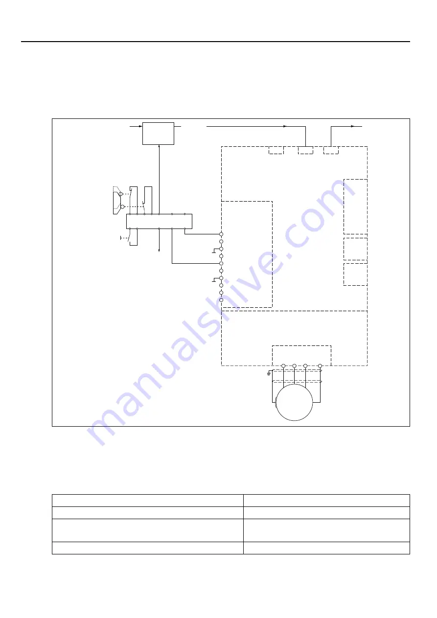
3.6.4 Wiring SS1
At tripping SS1 (Safe Stop 1) the drive is only disconnected from supply when it has reached
a standstill [IEC 61800-5-2]. The stop mode is not directly requested, but the maximum time
until reaching the standstill is estimated. This period is loaded in a safe time relay, which dis-
connects the drive finally from supply.
U V W PE
M
X1A
X4A
Terminal strip X2B
Diagnosis
Power circuit
Control circuit
open
closed
S1
S2
Safety device
Receipt
X2A.13
Safety module
1 - STO1+
2 - STO1+
3 - STO1-
4 - STO1-
5 - STO2+
6 - STO2+
7 - STO2-
8 - STO2-
9 - STO-OUT
10 - STO-OUT
X2A
X2C
X2D
Field bus
Motion
Control
X4B
Field bus
X4C
Field bus
When pressing the emergency stop unit the drive is stopped with a deceleration ramp via
input X2A.13 (I3).
Simultaneously the expiration of the safe time occurs in the safety module. After expiration of
the safe period the control signals STO1+ und STO2+ (X2B.1 and 5) are removed and thus
the energy supply of the drive is disconnected.
The following adjustments must be done in the drive module for the function „drive stop“:
Parameter
Adjustment
pn29 „prg. error stop. mode“ (Index 0x2A1D)
1: dec. ramp -> Fault
pn48-59 (0x2A30-0x2A3C)
Adjustment of the deceleration and jerk
values for the adjusted error reaction
pn30 „prog. error source“ (Index 0x2A1E)
4: I3 (here in the example)
Содержание COMBIVERT S6 Series
Страница 2: ......
Страница 32: ...GB 31 Notices...