


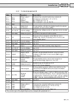


GB - 24
5
Operating the Unit
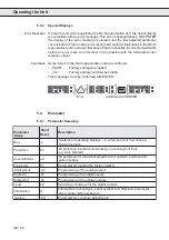
5.1
Initialization
Initialization
After connection to the mains supply the R4-S-regenerative unit is initialized.
First the power part is identified. The error message „E.PUC” (Power Unit Check)
is displayed when there is an unvalid power part. A reset of this error is not
possible, the power part must be checked.
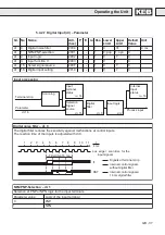
Status „SYn“
The R4-S-regenerative unit goes into status „SYn” when there is a valid power
part. During this synchronisation phase the following processes are running:
1. Check the correct synchronisation connection, (if the synchron signal is mis-
sing, the error „E.nEt” is displayed)
2. Check the phase assignment of synchron signals to the mains phases. Error
message „E.SYn” is displayed when one phase is missing or when there is a
phase assignment error.
After synchronisation the actual mains frequency is set and the connection of
the R4-S-regenerative unit is correct. If the release signal (terminal ST) is set,
the R4-S-regenerative unit takes independently its function. Dependent on the
actual demand the R4-S-regenerative unit is in the status „Active” or „Stdby”.
Status „Stdby“
The R4-S-regenerative unit defects a normal voltage level in the DC-bus of the
connected frequency inverter (mot. operation) and the modulation signals of the
R4-S-regenerative unit are not active.
Status „Activ”
The modulation signals become active and the unit goes into feedback operation
when there is an overvoltage. The R4-S-regenerative unit is active, also if another
R4-S-regenerative unit in the system demands a feedback operation (Signal
RS=1).
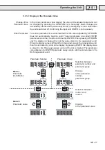
5.2
Operation during the Unit is running
Generally there are two options of operation with the R4-S-regenerative unit:
1. Operation with interface-operator
2. Operation with personal computer and system software COMBIVIS
Operating the Unit
Содержание COMBIVERT R4-S
Страница 1: ...00 R4 S10 K150 BETRIEBSANLEITUNG INSTRUCTION MANUAL COMBIVERT Version 1 5 04 03...
Страница 48: ...GB 48 Notice...
Страница 50: ...GB 50...