


KE RT Series UPS 6-10kVA UL 208-220-230-240Vac User Guide English 20180130 This manual is for qualified personnel only
- 29 -
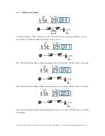
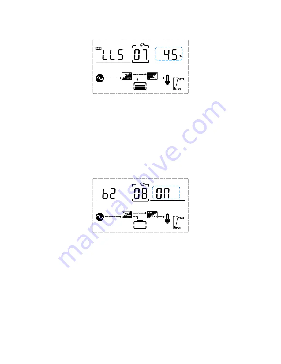
5.4.7
Bypass Volt-Lo setting
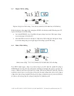
Bypass voltage lower limit setting – Note: the area marked by the broken-line will be flashing.
Within the bypass voltage upper limit setting press DOWN or within the parallel ID setting press UP,
it goes to the bypass lower limit setting.
•
Use button ENTER/ON (to set the different bypass voltage lower limit. The bypass voltage
lower limit range is 20%,30%,45%.
•
Press ESC/OFF button to exit the bypass voltage lower limit setting (save the bypass voltage
lower limit setting) and goes to bypass upper limit setting or parallel ID setting.
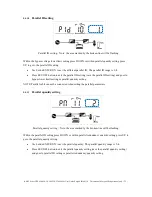
5.4.8
Buzzer Mute Setting
Buzzers mute setting – Note: the area marked by the broken-line will be flashing.
Press DOWN under bypass voltage lower limit setting or press UP under the parallel ID setting to
ENTER the buzzer setting. Now the setting status is flashing as the Figure shows (note: on=mute; off=
no mute). When pressed, it shows the mute cycle setting, the selection includes ON and OFF. (Press the
up button or down button to exit the mute setting (save the mute setting status) and switch to bypass
voltage lower limit setting or parallel ID setting (note: when in stand-alone mode, press down button to
exit and save the settings, then the settings is completed for stand-alone unit).


