


Q.1.23 November 2014
Page 17
Mounting the Controller
Once the wiring has been run to the controller location, the controller
can be connected. When installing the KE2 Controlled Environment,
the (4) screws supplied in the kit may be preinstalled in the mounting
surface. The controller has keyholes in each mounting tab to allow
the controller to be installed over the screws. The mounting pattern
can be seen in Figure 10.
User Interface
The KE2 Controlled Environment’s onboard user interface uses a
familiar 6-button arrangement to simplify navigation through the
controller’s menus. The menu has been grouped by category to pro-
vide an easy to program structure. By grouping the menu by each
functional area, the user is not required to scroll though unrelated
setpoints to access the desired functionality.
The left and right arrows move between the categories. When
pressed while in a menu, the left and right arrows will move to the
main screen or the adjacent menu.
The up and down arrows move the user through the available op-
tions for each group. All users are allowed access to the variable
alarms. All other information is password protected to prevent unau-
thorized access to the controller’s functionality.
Use ENTER button to save an input option when it has been changed.
Button must be held for 3 seconds to prevent accidental changes.
Changes may be discarded by waiting, to allow the controller to time-
out and return to default screen, or pressing BACK button.
The BACK button is used to return to the previous screen. Pressing
the BACK button twice at any time will return the user to the default
view. See Table 2 (following page).
Controller Setup
Upon initially applying power to the controller, the controller will ini-
tialize, then automatically enter the Introduction Mode. The Intro
Mode consists of as little as 4
setpoints that must be configured for
KE2 Controlled Environment to begin controlling the system.
Table 1 shows the Intro Mode. The first setpoint the user is asked to
enter is the desired ROOM TEMP. This is followed by the TARGET
HUMIDITY, then DEFROST TYPE. The controller is designed to work
with electric, hot gas, and off time defrosts. The last setpoint is the
VALVE TYPE. The controller is defaulted to be used with a KE2 EEV,
but may be used with a mechanical valve or a customer defined valve.
These are the only setpoints required to begin controlling the system,
when applied on a single evaporator with a mechanical valve, See
Table 1.
Adjusting Controller Parameters
The controller has the ability to access an abundance of informa-
tion from the 4-digit alphanumeric display. However, the controller
requires a password, adding a degree of protection from unwanted
modifications. The controller will prompt the user for a password
PASSWORD when the user attempts to access setpoints they do not
have permission to change.
Table 2 shows the menu structure of the controller. The default dis-
play of the controller always displays the actual room temperature.
Pressing the up and down arrows moves the display through the
VARIABLES menu. See Table 2 By default, the controller only allows
access to the room temperature. The VARIABLES menu consists of
the current sensor readings and the relays’ state. The User Password
(1111) only provides access to the ROOM TEMP setpoint.
For the protection of the system, access to the SETPOINT and
MANUAL control requires an Installer Password (2222). Pressing
the right or left arrow will move from the Variables menu to the next
menu, shown in Table 2, a complete list of parameters are shown in
Table 3.
Pressing the BACK key at any time will return the user to next level
up the menu. A second press will either return to the Main Menu or
to the room temperature reading.
Table 1 - Introduction Menu
Mechanical Valve TEV
4 steps
KE2 HSV
(default)
5 steps
Custom EEV
7 steps
Room Temp
Room Temp
Room Temp
Target Humidity
Target Humidity
Target Humidity
Defrost Type
Defrost Type
Defrost Type
Valve Type
Valve Type
Valve Type
Refrigerant
Refrigerant
Step Rate
Max Steps
If using a standard/predefined EEV, the user will also be prompted
to specify the REFRIGERANT. Once these have been set, the KE2
Controlled Environment will begin controlling EEV and the system.
Table 3
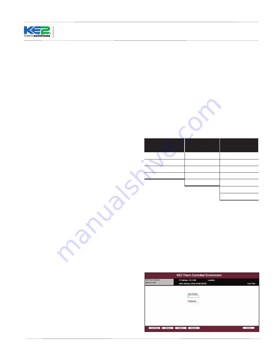
Web Login
When accesssing the controller using the webpage, the Username
and Password are required.
The defaults are set as: User: ke2admin
Password: ke2admin
IMPORTANT: The Password should be changed from the default
for security purposes.
KE2
Controlled
Environment
Quick Start Guide
Wine Cellar 2
ke2admin
ke2admin
© Copyright 2014 KE2 Therm Solutions, Inc., Washington, Missouri 63090


