18
Installation Variation #1: Supplement for boats using a key-switch for single engine starting.
For use with MKSMXXX00 Models
NOTE:
The PLC inside the MKSM needs power (approximately 2.5 amps) from a source, such
as a key switch, that provides power only when the boat is in operation. Consider this
additional 2.5 amps of power and how it may affect the reliability of the source. This
new circuit should be protected with a 5-amp fuse or circuit breaker per ABYC
standards, and it should in no way affect the integrity of the engine’s starting or running
operation.
NOTE:
The following install variation is an
alternate method
for installations on vessels with
key-switch starting.
When installing MKSM on a boat that incorporates key switch starting, no rocker switch or
push button replacement switch is required.
NOTE:
If the OEM engine manufacturer or the boat builder reviews the KBI MKSM Theory of
Operation (page 13 + 14) and the requirements for DPST-type functionality, then
incorporating the DPST-type function and engineering it into the factory build key-
switch should be no problem. However, when installing a MKSM on a boat that has
already been built with key-switch starting, the following procedure and hardware
(wiring) should be used.
NOTE:
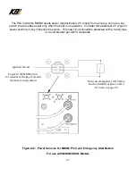
If battery power was insufficient (
˂
7 volts), too weak to enable an engine start or
provide adequate power to the “S” terminal, an emergency start button should be
installed (installed near the controls) and would supply capacitor power to enable the
entire MKSM system when the button is pushed.
Содержание KAPower MKSM Series
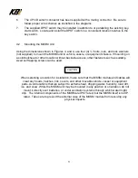
Страница 10: ...10 Figure 2 Typical Cable Installations ...
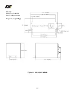
Страница 11: ...11 Figure 3 Six 6 Cell MKSM Material Shell 16ga SS 304 2B Cover 18ga SS 304 2B Weight 21 5lb 9 75Kg ...
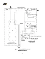
Страница 17: ...17 Figure 6 Standard MKSM Schematic MKSMXXX00 Models ...
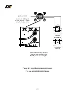
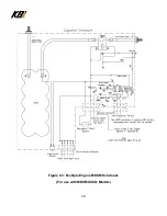
Страница 28: ...28 Figure C3 Multiple Engine MKSM Schematic For use with MKSMXXX01 Models ...

