WESII User Manual
Manual-WESII-Rev1205A
Copyright © KBC Networks 2012
Page 15 of 48
www.kbcnetworks.com
Cannot be connected to a PoE port on a switch, the power injector must be
used.
WESII radios cannot communicate via RF link and cable connection
simultaneously.
A crossover cable is not necessary if the two PIMs connect into an Ethernet
switch.
Note:
Type of Cat5 configuration may be determined by LAN port of the Ethernet
device. If the port is a 10/100 port, you may require a crossover cable. Most cables
used to connect the WES system are configured using a straight-through color code.
2.4.8
Aligning Directional Antennas
Within the Graphical User Interface (GUI) there are several helpful diagnostic tools.
Following is a short explanation to use the RSSIs for further antenna alignment.
Please see the GUI description in section 3 for further details.
To get to this information, first connect to the RF modules via their respective IP
addresses (see section 3) using a web browser from a laptop connected to the
WESII.
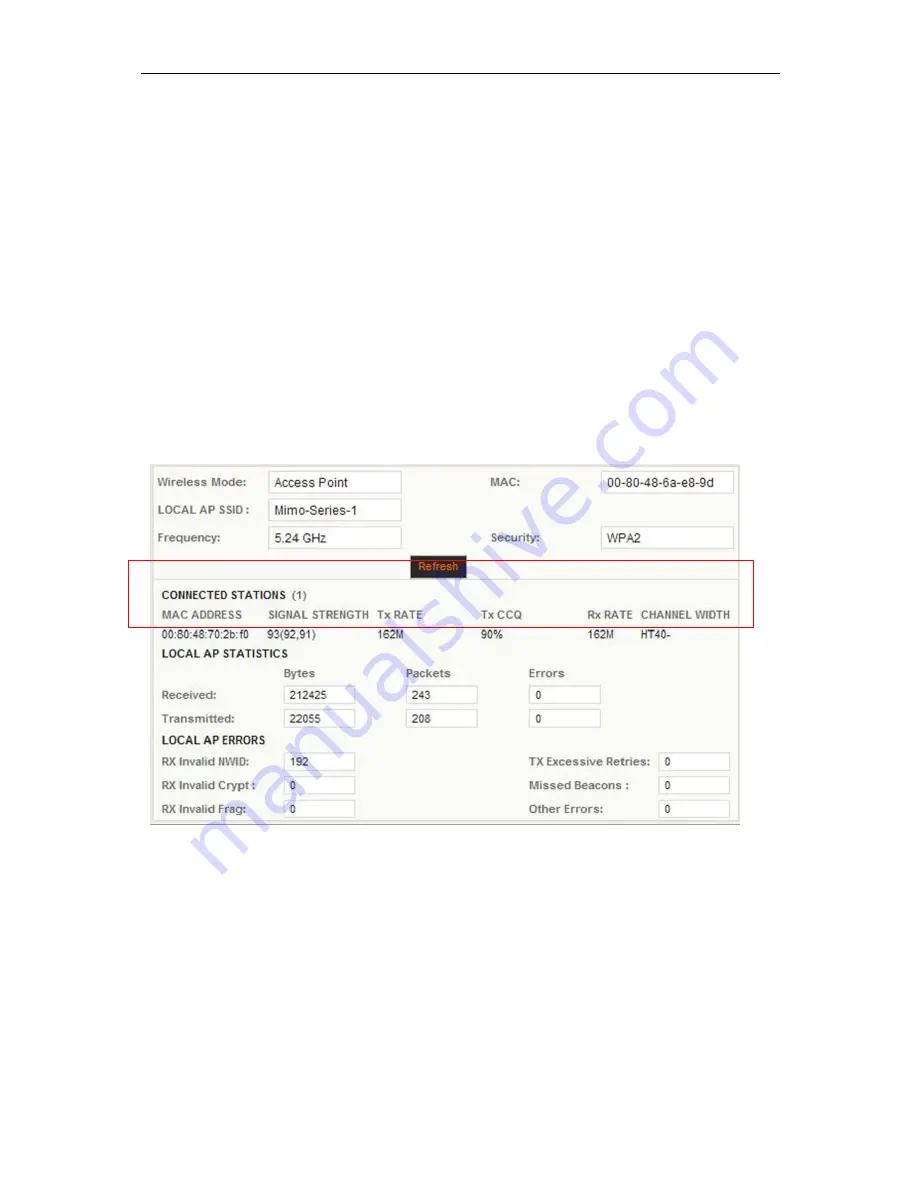
In the screen shot taken from a Ptp Host/AP with one Client connected above, the
section referenced in this portion of the manual is highlighted with the red lined box.
The information needed for the alignment is found under “SIGNAL STRENGTH”. The
RSSI is the number next to the parenthesis. The higher the number, the more signal
strength on the link. Generally this number will be lower than pictured. When
aligning, perform the following procedure:
Loosen the mounting assembly and move the RF Module slightly in a downward
angle. Make the movement no more than a couple of centimeters. Then refresh the
browser three or four times so that the connection can settle in. Note the RSSI and
continue moving the antenna downward, refreshing and noting the RSSI numbers.
Continue until the RSSI decreases. Then in an upward angle, perform the same


