


29
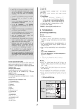
4.2 Selecting and Preparing the
Refrigerant Piping
Schematic diagram of the allowable length and height difference for refrigerant piping
4.2.3 Piping and component definition
Table 4-2
Definition
Pipe connection position
Code
Branch joint
L2~L5
L1
Main pipe
Indoor unit
Indoor unit
main pipe
Indoor unit
auxiliary pipe
The pipe between the outdoor unit
and the first branch joint.
The pipe between the branch joints.
N1~N6
/
The pipe between the indoor unit
and the nearest branch joint.
a~f
A~E
The joint connect with the main
pipe, the indoor unit main pipe
and auxiliary pipe.
4.2.1 Refrigerant piping requirements
4.2.2 Design considerations
Foreign objects in the pipes (including lubricant used
during pipe bending) must be ≤ 30 mg/10 m.
Calculate all piping lengths and distances.
The R32 refrigerant pipeline system must be
kept strictly clean, dry and sealed.
NOTE
Cleaning and drying: prevent foreign objects
(including mineral oil or water) from mixing
into the system.
Seal: R32 does not contain fluorine, does not
destroy the ozone layer, and does not deplete
the ozone layer that protects the earth from
harmful ultraviolet radiation. But if it is
released, R32 can also cause a slight
greenhouse effect. Therefore, you must pay
special attention when you check the quality
of the installation seal.
The piping and other pressure vessels must
comply with the applicable laws and be
suitable for use with the refrigerant. Use only
phosphoric acid deoxidized seamless copper
for the refrigerant piping.
The amount of brazing required should be kept
to a minimum.
As bends cause pressure loss when
transporting refrigerant, the fewer bends in the
system, the better it is. Piping length needs to
take the equivalent length of bends into account
(the equivalent length of each branch joint is 0.5
m).
On the two inside sides of the first branch joint,
the system should, as far as possible, be equal
in terms of the number of units, total capacities
and total piping lengths.
The refrigerant shut-off device (RSD) is
optional. Please contact the local dealer for
purchase. Referigerant shut-off device shall be
located outside, installed on the main pipe and
close to the first branch joint. For more detailed
instructions, please refer to the corresponding
installation and operation manual.
NOTE
Figure 4-7
Outdoor Unit
a
N1
3
N
5
N
6
N
2
N
4
N
b
c
e
f
d
1
L
2
L
5
L
3
L
4
L
A
B
C
D
E
Maximum level dif
ference between the
outdoor unit and indoor unit is ≤ 50 m
Maximum level dif
ference between Indoor
units is ≤ 15 m
Maximum piping length from the first branch joint
to the farthest indoor unit is ≤ 40 m
Maximum equivalent piping length from the outdoor
unit to the farthest indoor unit is ≤ 120 m
First branch
joint
Refrigerant shut-off
device(Optional)
RSD