


Wiring
BEFORE PERFORMING ANY
ELECTRICAL WORK, READ THESE
REGULATIONS
1. All wiring must comply with local and national
electrical codes, regulations and must be
installed by a licensed electrician.
2. All electrical connections must be made
according to the Electrical Connection Diagram
located on the panels of the indoor and outdoor
units.
3. If there is a serious safety issue with the power
supply, stop work immediately. Explain your
reasoning to the client, and refuse to install the
unit until the safety issue is properly resolved.
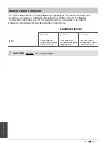
4. Power voltage should be within 90-110% of
rated voltage. Insufficient power supply can
cause malfunction, electrical shock, or fire.
5. If connecting power to fixed wiring, a
surgeprotector and main power switch should
be installed.
6. If connecting power to fixed wiring, a switch
or circuit breaker that disconnects all poles and
has a contact separation of at least 1/8in (3mm)
must be incorporated in the fixed wiring. The
qualified technician must use an approved
circuit breaker or switch.
13.
Make sure that you do not cross your
electrical wiring with your signal wiring.
This may cause distortion and
interference.
14.
The unit must be connected to the
main outlet. Normally, the power supply
must have a impedance of 32 ohms.
15.
No other equipment should be
connected to the same power circuit.
16.
Connect the outdoor wires before
connecting the indoor wires.
7. Only connect the unit to an individual branch
circuit outlet. Do not connect another
appliance to that outlet.
8. Make sure to properly ground the air conditioner.
9. Every wire must be firmly connected. Loose
wiring can cause the terminal to overheat,
resulting in product malfunction and possible fire.
Do not let wires touch or rest against refrigerant
tubing, the compressor, or any moving parts
within the unit.
If the unit has an auxiliary electric heater, it must
be installed at least 1 meter (40in) away from
any combustible materials.
To avoid getting an electric shock, never touch
the electrical components soon after the power
supply has been turned off. After turning off
the power, always wait 10 minutes or more
before you touch the electrical components.
10.
11.
12.
WARNING
BEFORE PERFORMING ANY
ELECTRICAL OR WIRING WORK,
TURN OFF THE MAIN POWER TO
THE SYSTEM.
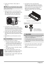
Wiring
Indoor unit
Outdoor unit
Air switch
(purchased seperately)
(purchased seperately)
Outdoor unit power wires
Indoor & Outdoor
connective wires
(A)
NOTE ON AIR SWITCH
When the maximum current of the air
conditioner is more than 16A, an air switch or
leakage protection switch with protective
device shall be used(purchased seperately) .
When the maximum current of the air
conditioner is less than 16A, the power cord of
air conditioner shall be equipped with plug
(purchased seperately) .
Page
31
Содержание KPCA-52
Страница 40: ......


