Kavan BETA 1400 RTF Скачать руководство пользователя страница 6

4

PREFLIGHT CHECK

CHECKING THE CURRENT SET-UP

1. Assure that the transmitter is turned on (both the LEDs are on with the 

T8FB), place all the trims in their neutral positions and set the throttle stick 

into the lowest position. Connect the flight pack to the ESC - the red LED on 

the receiver must glow. If it blinks or does not glow at all, the receiver and 

transmitter require establishing their link by the binding procedure - refer to 

the page 6 in this manual.

2. Checking the control surface neutrals

Please check all the control surfaces are in the neutral position if the corre-

sponding transmitter sticks and trims are in the centre position. If not, please 

loosen the setting screw of the corresponding push rod connector and set 

the control surface to the neutral position. The elevator and rudder has to be 

flush with the horizontal stabilizer resp. the fin, both two ailerons have to be 

flush with the wing trailing edge. Once satisfied, apply a drop of threadlocker 

to the setting screw a tighten it.

CAUTION:

 If the quick link got loose during flight, your model could become 

partly or completely uncontrollable. Therefore, you should check the linkage 

regularly.

3. Testing the Ailerons

A) Move the aileron stick to the left; (looking from the tail to the nose) the left 

aileron must move up and the right aileron must drop down simultaneously. 

B) Move the aileron stick to the right; the left aileron must drop down and the 

right aileron go up simultaneously. 

C) Return the aileron stick to the centre (neutral) - both two ailerons will re-

turn to the neutral position.

Note: If the ailerons are moving in the opposite direction, you will have to 

reverse the direction by flipping the aileron reverse switch (AIL) on your 

transmitter.

4. Testing the Rudder

A) Move the rudder stick to the left; (looking from the tail to the nose) the 

rudder must move to the left. 

B) Move the rudder stick to the right; the rudder must move to the right. 

C) Return the ruder stick to the centre (neutral) - the rudder will return to the 

neutral position. 

Note: If the rudder is moving in the opposite direction, you will have to re-

verse the direction by flipping the rudder reverse switch (RUD) on your trans-

mitter.

5. Testing the Elevator

A) The elevator stick is located on the left side on the Mode 1 transmitter or 

on the right side on the Mode 2 transmitter. Pull the elevator stick down; the 

elevator must move up). 

B) Push the elevator stick up; the elevator must move down. 

C) Return the elevator stick to the centre (neutral) - the elevator will return to 

the neutral position. 

Note:

 If the elevator is moving in the opposite direction, you will have to 

reverse the direction by flipping the elevator reverse switch (ELE) on your 

transmitter.

6. Control Surface Throws

If you carefully followed the instruction in the previous sections of this man-

ual, the correct default control surface throws has been set automatically. 

The control throws are set by the ratio between the length of the servo arm 

and the control surface throw - the actual throws set this way are listed in the 

column “Normal Rate” in the table below. (

The throws are always measured 

in the widest point of the particular control surface.

) It is always better to try 

to reach the requested throws mechanically, adjusting the arm/horn length 

ratio - even if you have got a fancy computer radio. If you got such a transmit-

ter you can use the function “Dual Rate” (D/R) to get even more forgiving set-

up - please refer to the “Low Rate” column. You can also do it mechanicaly 

- simply move the push rod Z-bends on the servo arms closer to the centre.

A. A radio featuring only one aileron channel

Control

Low Rate

Normal Rate

Expo*

Aileron

7 mm up and down

10 mm up and down

10-20%

Rudder

10 mm left and right

12 mm left and right

0-10%

Elevator

6 mm up and down

8 mm up and down

20-30%

B. A radio featuring 2 independent aileron servo channels

Control

Low Rate

Normal Rate

Expo*

Aileron

8 mm up/4 mm down

10 mm up/5 mm down 10-20%

Aileron 

(Airbrake)

13 mm up

13 mm up

-

Rudder

10 mm left and right

12 mm left and right

0-10%

Elevator

6 mm up and down

8 mm up and down

20-30%

Elevator 

(Airbrake)

2 mm up

2 mm up

-

*Expo – set to decrease the sensitivity around the neutral (Futaba, Hitec, Radi-

olink, Multiplex: -10/-20, Graupner: +10/+20 etc.) 

7. Testing the Power system

KAVAN T8FB/R-20B: Check the throttle channel reverse switch (THR) is in the 

“N“ (up) position on the transmitter. Now perform the throttle range calibra-

tion procedure as described in the KAVAN R-20B manual (refer to the attach-

ment) and check the motor brake function has been turned on. 

A) Turn on the transmitter, set the throttle stick to the lowest position, con-

nect the flight pack to the ESC in the model (ESC has to be set to the “Brake 
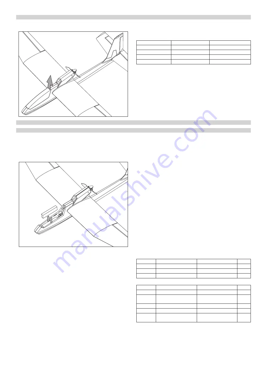
RC SET INSTALLATION

Now you have to install/connect your receiver, servos and electronic speed 

controller (ESC). 

1. Remove the canopy; lift the rear part up to disengage the magnetic lock.

2. Following you radio instruction manual connect the servos and ESC to 

your receiver – the table shows the channel assignment of the T8FB radio 

supplied in the RTF kit:

Connector Label

Function

Receiver Channel (T8FB)

AILE

Ailerons

CH1

ELEV

Elevator

CH2

ESC

Throttle

CH3

RUDD

Rudder

CH4

3. Put your receiver into the fuselage (into the rear part of the cockpit); you 

can secure it using a strip of hook-and-loop tape to the fuselage.

4. The flight battery pack is to be inserted into the nose of your BETA 1400 

and secured by the hook-and-loop tape to the fuselage - the exact po-

sition of the battery pack will be determined later during the Centre of 

Gravity position check.

CAUTION: Always turn on your transmitter first and only then connect 

the flight pack to the ESC. From now on always handle your model as if 

the motor might burst into life and the propeller start to spin anytime!

Содержание BETA 1400 RTF

Страница 1: ...den apod Vyhle dejte bezpe n m sto mimo cesty a ve ejn komunikace dbejte na bezpe nost p ihl ej c ch div k VORSICHTSMA NAHMEN Dieses R C Modell ist kein Spielzeug Benutzen Sie es mit Vorsicht und halt...

Страница 2: ...nalreception Youcanbenditifnecessary carefullyandnot in a sharp angle a gentle arc is what are we looking for here The aerial should be secured e g to the side of fuselage with strips of sticky tape T...

Страница 3: ...for operating it in a manner that does not endanger yourself and others or result in damage to the product or the property of others This model is controlled by a radio signal that is subject to inter...

Страница 4: ...ocket 230 V 50 Hz All the LED glow green and flash red indicating the charger is ready to charge 3 Plug the balance connector of your flight battery JST XH into the corre sponding socket on the charge...

Страница 5: ...se two 20 30 ccm extension cables not supplied in the kit to connect aileron servos to your receiver typically CH1 and CH5 or CH6 it depends on the transmitter and its setting please refer to the inst...

Страница 6: ...evious sections of this man ual the correct default control surface throws has been set automatically The control throws are set by the ratio between the length of the servo arm and the control surfac...

Страница 7: ...ing The model must be launched into wind every time Throw grass into the air to observe the wind direction Turn on your transmitter Connect and put the flight pack into the battery compartment and sec...

Страница 8: ...rn also works like a rudder fortunately it helps to maintain the turn In practise the ailerons are used to put your model to the desired angle of bank the rudder is used to maintain it and the elevato...

Страница 9: ...CALIBRATION The KAVAN ESC features Automatic Throttle Calibration to ensure the smoothest throttle response and resolution throughout the entire throttle range of your transmitter This step has to be...

Страница 10: ...ill be temporarily changed to normal mode to get rid of the chance of a crash caused by slow throttle response This special design is suitable for aerobatic flight when quick throttle response is need...

Страница 11: ...n je u 2 4GHz RC souprav velmi mal Nikdy tak nelze zcela vylou it mo nost n jak z vady na modelu nebo pilot n chyby tak e je vhod n v dy l tat s mo delem tak aby se v ech sm rech nach zel v bezpe n vz...

Страница 12: ...lizuj e nab je je v pohotovostn m re imu a je p ipraven nab jet 3 Servisn konektor va eho akumul toru konektor syst mu JST XH zapojte do odpov daj c z suvky na p edn stran nab je e 4 Nab je za ne nab...

Страница 13: ...0 30 cm prodlu ovac kabely nejsou sou st stavebnice zapojte je do kan l pro lev a prav k id lko na p ij ma i typicky kan l 1 a kan l 5 nebo 6 z le na typu a nastaven RC soupravy i te se dle n vodu k o...

Страница 14: ...vka pohybovala v opa n m smyslu p epn te p e p na smyslu v chylek na vys la i RUD 5 Zkou ka ovl d n v kovky A Na vys la i v M du 1 je ovlada v kovky vlevo v M du 2 napravo Pokud nyn vych l te ovlada v...

Страница 15: ...ada e v kovky m e b t dokonce zapot eb v kovku m rn potla ovat aby se model nesna il stoupat a p li Pokud BETA 1400 po vypu t n ztr c v ku p it hn te ovlada v kovky pon kud jen m lo k sob a model za n...

Страница 16: ...en s pou it m sm rovky postupujeme podobn model nejd ve uvedeme k id lky do n klonu a s mal m zpo d n m vych l me sm rov ku a p it hneme v kovku pr v tak aby model dr el st l n klon a v klouza v m let...

Страница 17: ...o kejte cca 2 s 3 Po 2 sekund ch motor vyd dv p pnut P p P p kter mi potvrzuje e rozeznal polohu pln plyn 4 Ihned pot st hn te ovlada plynu zcela dol M lo by se ozvat n kolik p pnut P p oznamuj c ch z...

Страница 18: ...ojen akumul toru motor nepracuje po dvojit m p pnut p p p p se ozve trylek 56712 Smysl v chylek kan lu plynu je opa n tak e regul tor p e el do pro gramovac ho re imu Nastavte spr vn smysl v chylek v...

Страница 19: ...wird durch ein Funksignal Ihrer Fernsteuerung gesteuert das abh ngig ist von vielen St reinfl ssen au er halb Ihrer Kontrolle Diese St rungen k nnen vor bergehend den Verlust der Kontrolle verursachen...

Страница 20: ...chwarzes Kabel Der Sender verf gt ber eine Schutzschaltung Wenn Sie den Stecker um gekehrt anschlie en funktioniert der Sender nicht wird jedoch nicht durch umgekehrte Polarit t zerst rt Wir empfehlen...

Страница 21: ...cm Verl ngerungskabel nicht im Kit enthalten um Querruderservos an Ihrem Empf nger anzuschlie en typischerweise CH1 und CH5 oder CH6 dies h ngt vom Sender und seinen Einstellungen ab siehe Bedienungs...

Страница 22: ...das H henruder muss exakt in die Neutralposition gehen Bemerkung Falls sich das H henruder in die falsche Richtung bewegt m s sen Sie die Servoumkehr am Sender ELE umschalten 6 Kontrolle der Ruderwege...

Страница 23: ...estartet werden Werfen Sie Gras in die Luft um die Windrichtung zu erkennen Schalten Sie den Sender ein Legen Sie den Flugakku in das Akkufach und stecken Sie ihn ein Befestigen Sie die Haube Halten S...

Страница 24: ...itenruder um das Modell im Kurvenflug zu hal ten und das H henruder um die H he zu halten und die Drehgeschwindig keit zu erh hen Alternativ k nnen Sie nur das Querruder nutzen um Ihr Modell in Schr g...

Страница 25: ...n k nnen Es ist deshalb in Ihrer Verantwortung zu pr fen da alle Steckverbindungen bevor Sie den Flugakku das erste Mal anstecken korrekt sind DAS ERSTE EINSCHALTEN DES KAVAN REGLERS AUTOMATISCHE GASK...

Страница 26: ...n Einige Motoren erfordern unterschiedliche Einstellungen so da wir empfehlen den vom Hersteller des Motors angegebenen Empfehlungen zu folgen zu stellen Bemerkung Lassen Sie den Motor zuerst am Boden...

Страница 27: ...mo no plne vyl i mo nos nejakej z vady na modeli alebo pilotnej chyby tak e je vhodn v dy lieta s modelom tak aby sa vo v etk ch smeroch nach dzal v bezpe nej vzdialenosti od oko lit ch predmetov a os...

Страница 28: ...el nab ja ky do elektrickej z suvky 230 V 50 Hz V et ky LED sa rozsvieti zelene a preblikuj erveno m signalizuj e nab ja je v pohotovostnom re ime a je pripraven nab ja 3 Servisn konektor v ho akumul...

Страница 29: ...k ble nie s s as ou staveb nice zapojte ich do kan lov pre av a prav kr delko na prij ma i typicky kan l 1 a kan l 5 alebo 6 z le na type a nastaven RC s pravy ria te sa pod a n vodu na obsluhu va ej...

Страница 30: ...slu prepnite prep na zmyslu v chyliek na vysiela i RUD 5 Sk ka ovl dania v kovky A Na vysiela i v M de 1 je ovl da v kovky v avo v M de 2 napravo Ak teraz vych lite ovl da v kovky dole pri poh ade na...

Страница 31: ...onca potrebn v kovku mierne potl a aby sa model nesna il st pa a pr li Ak BETA 1400 po vypusten str ca v ku pritiahnite ovl da v kovky trochu len m lo k sebe a model za ne st pa Krok 2 Lietanie s mode...

Страница 32: ...i do n klonu s mal m oneskoren m vych lite smerov ku a pritiahnite v kovku pr ve tak aby model dr al st ly n klon a v k zavom lete str cal o najmenej v ku Zapojenie smerovky do riadenia so prejav nasl...

Страница 33: ...ako prv kr t pripoj te pohonn akumul tor PRV ZAPNUTIE REGUL TORA A AUTOMATICK KALIBR CIA PLYNU Regul tor je vybaven funkciou automatickej kalibr cie pre dosiahnutie vysok ho rozl e nia a plynul odozv...

Страница 34: ...p lmi motory s rota n m pl om Vo v ine pr padov stredn alebo n zke nastavenie asovania funguje s v inou motorov Pre dosiahnutie vy ej innosti odpor ame pre dvojp lov motory nastavova N zke a sovanie a...

Страница 35: ...U Ne iaduce zariadenia m ete dopravi do najbli ieho zariadenia na zber alebo recykla n ho strediska Zariadenie potom bud likvidovan alebo recyklovan bezpe n m sp sobom zadarmo Odovzdan m ne iaduceho z...

Страница 36: ...ovan modelu nem e sa predpoklada ani prija iadna zodpovednos za kody spojen s pou van m u vate om zostaven ho modelu Okami hom kedy sa u vate rozhodne pou i n m zostaven model preber v etku zodpovedn...

Отзывы: