background image


Operating Manual 


Original Operating Manual


Contents 

Page


1.


Introduction

 ............................................................................................................................................. 4 


1.1


Working with this manual ......................................................................................................... 4


1.2


Warning notes and symbols ..................................................................................................... 4


1.3


Copyright .................................................................................................................................. 4


1.4


CE-Mark ................................................................................................................................... 5


1.5


Qualified and authorised personnel ......................................................................................... 5


1.6


Warranty claims based on defects ........................................................................................... 5


1.7


Limits of applicable use ............................................................................................................ 5 


2.


Safety aspects

 ......................................................................................................................................... 6 


3.


Design

 ...................................................................................................................................................... 7 


3.1


Proper use of the equipment .................................................................................................... 7


3.2


Improper use ............................................................................................................................ 8 


4.


Installation and checking out

 ................................................................................................................ 8 


4.1


Installation ................................................................................................................................ 8


4.1.1


Fork Positioner with sideshift ....................................................................................... 9


4.1.2


Fork Positioner without sideshift ................................................................................ 10 


4.2


Checking out .......................................................................................................................... 11


4.2.1


Bleeding the hydraulic system ................................................................................... 11


4.2.2


Adjustment after putting into service .......................................................................... 11 


5.


Operation

 ............................................................................................................................................... 11 


5.1


General................................................................................................................................... 11


5.2


Load handling ......................................................................................................................... 12


5.3


Driving .................................................................................................................................... 12 


Содержание T 163N

Страница 1: ...03 15 Subject to modifications Fork Positioner T 163SN T 163N T 163SN Fork positioner with fork carrier for ISO 2330 forks with sideshift and mechanical synchronism T 163N Fork positioner with fork carrier for ISO 2330 forks without sideshift and mechanical synchronism ...

Страница 2: ...d on defects 5 1 7 Limits of applicable use 5 2 Safety aspects 6 3 Design 7 3 1 Proper use of the equipment 7 3 2 Improper use 8 4 Installation and checking out 8 4 1 Installation 8 4 1 1 Fork Positioner with sideshift 9 4 1 2 Fork Positioner without sideshift 10 4 2 Checking out 11 4 2 1 Bleeding the hydraulic system 11 4 2 2 Adjustment after putting into service 11 5 Operation 11 5 1 General 11 ...

Страница 3: ...the Operating Manual 20 12 EC Declaration of Conformity Summary 21 Our service department in Aschaffenburg will be happy to answer your technical questions and to provide additional support Technical Support 0049 0 6021 865 395 0049 0 6021 865 284 0049 0 6021 865 352 Orders for spare parts Domestic 0049 0 6021 865205 0049 0 6021 865251 Orders for spare parts Export 0049 0 6021 865344 0049 0 6021 8...

Страница 4: ... following symbols are used in this operating manual to highlight details of special importance Identifies details relating to do s and don ts for the purpose of avoiding injury and property damage Specific details relating to the efficient use of the attachment and other advice Lists are denoted by a shadowed box Steps to be performed by the operator are denoted by a black dot 1 In illustrations ...

Страница 5: ...onents Inappropriate installation maintenance inspection and servicing Assignment of unqualified or non authorised personnel Claims raised by third parties 1 7 Limits of applicable use KAUP attachments are intended for use under the following climatic conditions Average ambient temperature for continuous operation 25 C Allowable maximum ambient temperature short term up to 1h 40 C Allowable minimu...

Страница 6: ...a safe distance away from moving reciprocating or rotating parts of the attachment to avoid danger of crushing pinching or entanglement Notify the responsible department person immediately of changes and faults in operation of the attachment that affect safety The attachment shall be shut down Use aids to vision e g mirrors camera etc where goods being transported obstruct vision Only allow work o...

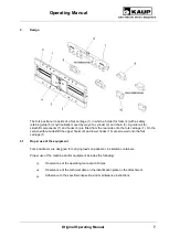
Страница 7: ...to the fork carriage 1 On the version without sideshift the upper hooks 9 and lower hooks 10 are screwed onto the fork carriage 1 3 1 Proper use of the equipment Fork positioners are designed for carrying loads on pallets or in skeleton containers Proper use of the machine and or equipment includes the following Observance of the operating manual at all times Observance of the technical data on th...

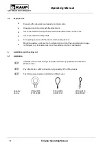
Страница 8: ...ting means Capacity 250 kg M16 1200 kg M16 2000 kg M16 Part no 9710160008 0360010201 0360010301 Exceeding the allowable load capacity and load centre Dragging or pushing loads with the attachment It is not permitted to transport loads which cause lateral forces on the forks It is not permitteld to clamp loads Transporting persons with the load or load handling devices Mounting auxiliary equipment ...

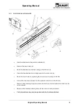
Страница 9: ... is correctly seated in the centre lock 4 Mount the lower hooks 2 tightening the screws 5 with a torque of 190 Nm Connect the hose lines 6 and 7 to the hydraulic connectors on the lift truck Remove safety retaining stops 8 and slide the fork tines onto the holder of the forks from the centre outward Make sure that all safety retaining stops 8 have been correctly reinstalled The fork positioner may...

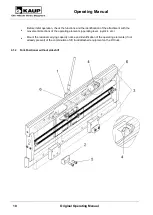
Страница 10: ...he attachment with the movement directions of the operating elements operating lever joystick etc Mount the residual carrying capacity notice and identification of the operating elements if not already present of the combination of lift truck attached equipment on the lift truck 4 1 2 Fork Positioner without sideshift ...

Страница 11: ...sition Inspect the hydraulic connections for leakage 4 2 2 Adjustment after putting into service The hydraulic system is under pressure During work on hydraulic components oil spurting out can cause injuries Unload the system in accordance with the operating instructions of the lift truck manufacturer In the case of injuries caused by high pressure oil inform the works physician and seek out a spe...

Страница 12: ...d comes into contact with the ground Ensure that multiple items stacked on top of one another are securely fastened 6 Maintenance and servicing 6 1 General Regular maintenance is essential to ensure reliable operation and long service life of the KAUP attachment Ensure that maintenance and servicing are performed by qualified and authorised personnel only Lubrication and cleaning work on the attac...

Страница 13: ... the following tightening torques which are valid for screws with connecting surfaces according to ISO 4762 ISO 4014 ISO 4032 etc Screw bolt rating 8 8 10 9 12 9 M6 thread 9 3Nm 14Nm 16Nm M8 thread 23Nm 33Nm 39Nm M10 thread 45Nm 66Nm 77Nm Μ12 thread 77Nm 115Nm 135Nm Μ16 thread 190Nm 280Nm 330Nm Μ20 thread 385Nm 550Nm 640Nm Failure of the safety devices e g the pressure relief valve and the non ret...

Страница 14: ...5 Foundry quality Teflon spray e g Wieds or Rivolta Only for plastic sections The specified maintenance schedules can change as a result of the operating conditions such as extreme cold heat and dust or poor ground conditions and this must be taken into account by the owner With other loads such as fork arms with a length of over 2 400 mm or raised load centres amended shorter maintenance interval...

Страница 15: ...rews 5 on the sideshift components 29 Screws 23 on the hooks 24 Screws 25 on the intermediate plates 26 Screws 27 on the hooks 28 Screws on the fork safety retaining stops 22 Screws on the chain tightener 15 und 16 Replace loose or damaged screws Torque the screws as specified in Chapter 6 1 General Weekly Grease Sliding pieces 2 by way of the greasing nipples 1 Supporting rollers 7 on the lower h...

Страница 16: ...t of the fork carriage 8 Loosen the lock nut 15 and turn the screw 16 fully out of the bolt 17 Replace the defective parts Refit the chain tightener device and holder for the forks again in the reverse order Replace defective supporting rollers 7 in the hooks 6 by removing the screws 4 Using suitable hoisting gear tilt the fork carriage 8 forwards away from the fork carriage on the lift truck Remo...

Страница 17: ...8 for wear Render the fork positioner inoperative when at least one of the three wear limits c2 k2 or d2 is underrun Wear limit z in mm ISO Kl 2 ISO Kl 3 ISO Kl 4 c2 k2 d2 c2 k2 d2 c2 k2 d2 13 5 11 5 9 3 18 5 14 5 13 2 22 0 17 5 15 6 As necessary For replacing the fork carriage please contact our service department ...

Страница 18: ...ty department 2 Before putting into operation carefully read and take note of the operating and security instructions 0100016401 3 Never reach into the unit as long as parts could still be moving due to the danger of squashing or shearing 0100016601 4 Use suspension point 0100015001 5 Test and operate the fork positioner with the fork arms attached only 0100000717 ...

Страница 19: ...leakage At cylinder Screw fitting is leaking Tighten seal screw fitting Sealing kit defective Replace sealing kit Piston rod scored Replace piston rod and sealing kit Sideshifter When shifting Too slow Pressure supplied by the FFZ too low Increase pressure at the FFZ Bore of the throttle valve is too small Re bore the throttle valve or replace it with a larger one Jerky shifting action Supporting ...

Страница 20: ...ational regulations Hydraulic fluids greases lubricants and soiled working materials Cleaning rags etc Packaging material Pallets straps cartons and plastic sheeting After decommissioning the attachment should be disposed of in accordance with local legislation and regulations 9 Transport During transport of the attachment care should be given to using appropriate means of support e g pallets Thes...

Страница 21: ... KG Braunstraße 17 D 63741 Aschaffenburg we hereby declare that the machinery Model Fork positioner Type T 163SN T 163N conforms to the latest valid version of the Machinery Directive 2006 42 EG The person authorised to compile the technical documents see EC Declaration of Conformity KAUP GmbH Co KG ...

Отзывы: