8
EN • Screen installation and operation manual
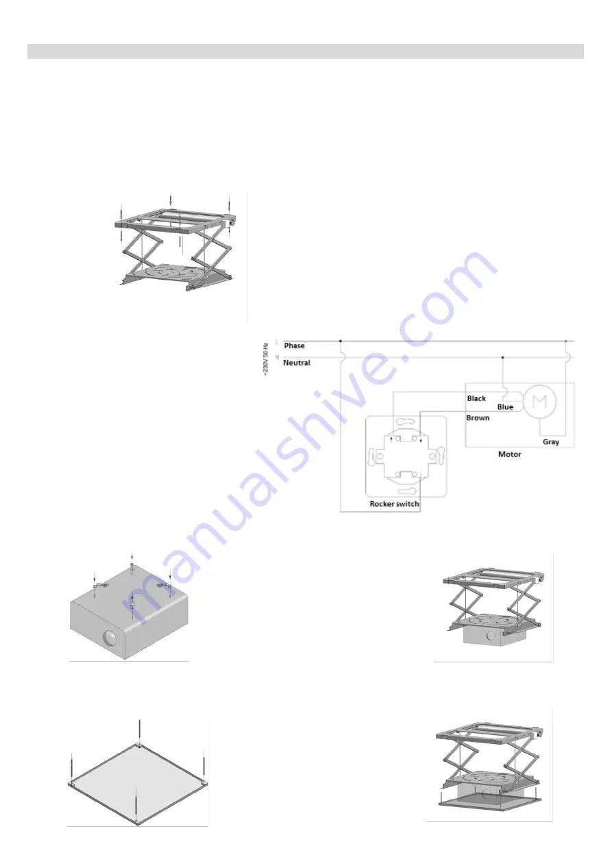
LIFT ASSEMBLY
1.
Assemble the base of the lift to the
structural ceiling using screws and
rawlplugs adequate to ceiling type
(assembly points are shown on the image
below). Remember to prepare an adequate
opening in the suspended ceiling for the
installation.(Fig. 1)
Fig 1
2.
Connect power supply to lift in order to make sure that the assembly was conducted correctly.
The lift can be controlled manually (switch) or with the help of the remote control (radio
steering).
Steering assembly requires only connecting the lift steering conductor to the controller /
switch.
Connect conductors in accordance with the color scheme below:
BROWN conductor
-
raises lift
BLACK conductor
-
lowers lift
BLUE conductor
neutral conductor
GRAY conductor
phase
Attention!!!
Before turning on the device make sure that all the connectors have been
connected in accordance with the manual.
Power connection should be conducted by a qualified electrician.
Power supply arrangement (example illustration pertains to rocker switch).
(
fig.2).
fig.2
3.
Fasten assembly grips to the projector
using provided screws.
(Fig. 3)
Fig.3
4.
Attach the projector, with fastened grips, to the lift’s bottom base. Slide in the projector from
the bottom and fasten to the top using provided screws (Fig. 4)
Fig.4
5.
Fasten the 4 threaded pins to the masking
panel as shown on the illustration below.
I
f the pins are too long they may be cut to
an appropriate length
(Fig. 5)
Fig. 5
6.
Attach the masking panel to the lift. Position the 4 pins in the openings on the base of the lift
and tighten the bolts as shown on the image below (Fig. 6)
Fig. 6


