
4 / 8
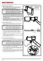
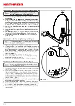
Kabelanschluss (Abb. 3)
1. Innensechskant-Schraube (S) am hinteren Ende der Haube
lösen, bis die Haube durch leichten Druck nach unten
①
ausrastet und abgenommen werden kann
②
.
Tipp
Wird nicht nur das Speisesystem ausgetauscht,
sondern eine Neuinstallation der Antenne vorge-
nommen, fahren Sie zuerst mit dem Punkt „Ausrichten
der Satelliten-Empfangsanlage“ fort und kehren im
Anschluss zum Punkt „Kabelanschluss“ zurück.
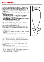
2. Beiliegende F-Stecker auf den Kathrein Kabeltyp LCD 95, 111
oder 115 montieren (siehe Abbildung) und am LNB anschließen.
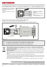
3. Beim Betrieb mit einem nachgeschalteten Multischalter auf die
korrekte Ausgangsbelegung achten (Versorgungsspannung nur
über LNB-Ausgang 1).
4. Angeschlossene Kabel nach vorne führen und seitlich in den Kabel-
halter eindrücken (siehe Vergrößerung in Abb. 3 unten) .
5. Haube aufschieben, bis sie in die Nut eintaucht und im unteren
Bereich einrastet. Innensechskant-Schraube (S) festziehen.
Cable connection (Fig. 3)
1. Loosen the Allen screws (S) at the rear end of the cover until the
cover can be unlocked by applying light downward pressure
①
;
remove cover
②
.
Tip
If the feed system is not only exchanged but a new
antenna system is being installed, proceed first as
described in the section “Aligning the satellite reception
system” and then return to “Cable connection”.
2. Mount the supplied F-type plug onto the Kathrein cable types
LCD 95, 111 or 115 (see figure) and connect to the LNB.
3.
When operating with a downstream multi-switch, make sure the
correct output is assigned (supply voltage only through LNB
output 1).
4. Lead the connected cable forwards and insert sideways into the cable
fastening (see close-up in fig. 3 below).
5.
Slide on the cover until it fits into the groove and locks in the bottom
section. Tighten Allen screw (S).
Raccordement de câbles (Fig. 3)
1. Desserrer la vis à six pans creux (S) à l’extrémité arrière du capot
jusqu’à ce que celui-ci puisse être déverrouillé d’une légère pression
vers le bas
①
et retiré
②
.
Avis
Si le système d’alimentation est remplacé et qu’une
nouvelle installation de l’antenne est effectuée, poursuivez
d’abord par le point « Orientation de l’antenne satellite »
puis revenez au point « Branchement des câbles ».
2. Monter les connecteurs F joints sur le câble Kathrein type LCD 95,
111 ou 115 (voir la figure) et les raccorder au LNB.
3.
En cas d’utilisation avec une commutateur multiple en aval, s’assurer
de la bonne correspondance des sorties (tension d’alimentation
uniquement par la sortie LNB 1).
4. Amener les câbles raccordés vers l’avant et les enfoncer latéralement
dans le support de câbles (voir l’agrandissement au bas de la fig. 3).
5. Mettre en place le capot qui doit entrer dans la gorge et s’enclencher
au bas. Serrer la vis à six pans creux (S).
Innensechskant-
Schraube (S)
Allen screw (S)
Vis à six pans (S)
①
②
Abb. 3
/ Fig. 3


