background image


Note:   

Please avoid any heavy thing placed on the switch. 

2.2 Power On 


Powering on the Switch, it will automatically initialize and its LED indicators will respond as       
follows:   
1)      All of the Link/Act LED indicators will flash momentarily, which represents a resetting of the       
system.   
2) The Power LED indicator will light all the time.   


Note:   

If the LED indicators don’t respond as described above, please check the power supply and its connection. 


Chapter 3. Identifying External Components 


This Chapter describes the front panel, rear panel and LED indicators of the Switch.         

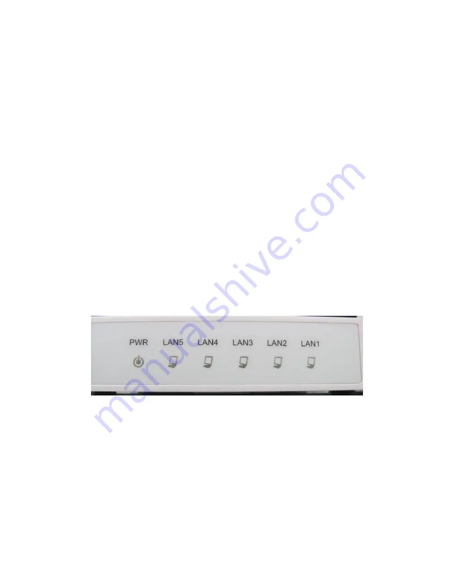
3.1 Front Panel   


Figure 3-1 KS105 Switch Front Panel   


The Switch’s LEDs are located on the front panel.   
Power LED:                                               
LANs (1-5):                                                                             

This indicator will light up when the Switch powers on.   
LED indicator will light green when a device is connected to the     
corresponding port. It flashes when data is being transmitted or received     
on the connection.   


Содержание KS105

Страница 1: ...KS105 Switch User Manual Shenzhen Kasda Digital Technology Co LTD ...

Страница 2: ...he Product 3 1 2 Features 3 Chapter 2 Installation 3 2 1 Mounting the Switch on a Desk 3 2 2 Power On 4 Chapter 3 Identifying External Components 4 3 1 Front Panel 4 3 2 Rear Panel 5 Chapter 4 Package Contents 6 Appendix A Specifications 6 Appendix B Troubleshooting 7 ...

Страница 3: ...and WLAN connectivity and an industry leading 5 FE of switching capacity all on a single chip 1 2 Features Complies with IEEE 802 3 IEEE 802 3u standards 5 10 100Mbps Auto Negotiation RJ45 ports supporting Auto MDI MDIX Supports IEEE802 3x flow control for Full Duplex mode and backpressure for Half Duplex mode Supports MAC address auto learning and auto aging LED indicators for monitoring power li...

Страница 4: ...dicators don t respond as described above please check the power supply and its connection Chapter 3 Identifying External Components This Chapter describes the front panel rear panel and LED indicators of the Switch 3 1 Front Panel Figure 3 1 KS105 Switch Front Panel The Switch s LEDs are located on the front panel Power LED LANs 1 5 This indicator will light up when the Switch powers on LED indic...

Страница 5: ...e Power socket is where you will connect the power adapter Please use the power adapter provided with this KS105 Switch The KS105 Switch is equipped with 5 10 100Mbps Auto Negotiation RJ45 ports where you will connect your network devices The working status can be indicated by the corresponding LEDs on the front panel ...

Страница 6: ...Auto aging IEEE 802 3x flow control for full duplex mode and backpressure for half duplex mode MAC Address Table 1k Forwarding Rate 10BASE T 14880pps port 100BASE TX 148800pps port Transmission Method Store and Forward Ports 5 10 100Mbps Auto Negotiation RJ45 ports Auto MDI MDIX Network Media 10Base T UTP category 3 4 5 cable maximum 100m EIA TIA 568 100Ù STP maximum 100m 100Base Tx UTP category 5...

Страница 7: ... and make sure the power source is ON 2 The LAN LED is not lit when a device is connected to the corresponding port Check to see if the cable connectors are firmly plugged into the Switch and the device and verify the connected device is turned on and working well Make sure the cable is not longer than 100 meters 328 feet ...

Отзывы: