background image

From the library of: Superior Sewing Machine & Supply LLC

Содержание DVC-200 SERIES

Страница 1: ... Mkasiseai Specif U S A Corp INSTRUCTION MANUAL DVC 200 SERIES MORIMOTO MFG CO LTD From the library of Superior Sewing Machine Supply LLC ...

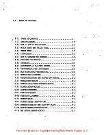
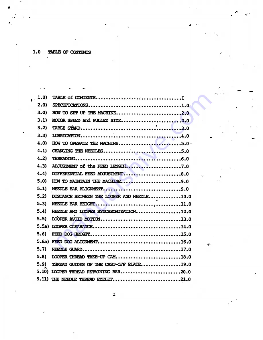
Страница 2: ...NT 8 0 5 0 HOW TO MAINTAIN THE MACHINE 9 0 5 1 NEEDLE BAR ALIOCffiNT 9 0 5 2 DISTANCE BE IWEEN THE LOOPER AND NEEDLE 10 0 5 3 NEEDLE BAR HEIOir 11 0 5 4 NETDLE AND LOOPER STNCHRONIZATICN 12 0 5 5 LOOPER AVOID MOTICN 13 0 5 5a LOOPER CLEARANCE 14 0 5 6 FEED DOG HEIGHT 15 0 5 6a FEED DOG ALIQ MEZir 16 0 5 7 NFTDTf GUAKD 17 0 5 8 LOOPER THREAD TAKE UP CAM 18 0 5 9 THREAD GUIDES OF THE CAST OFF ELATE ...

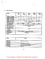
Страница 3: ...ECHANISM plain 1 plain plain differ 1 plain STITCH LENGTH 8 YO stitches peic inch NORK SPACE BEHIND OIHE Ji E LEJAR 235 cnn DIAMETER OF THE CYLINDER 65 mm LUBRICATION FULLY AUTOMATIC LUBRICATION SYSTEM RECOMMENDED SPEED 3500 rpm ii MODEL GAUGE DVC 202R 5 32 3 16 7 32 1 4 DVC 202RM DVC 202S 1 8 5 32 3 16 7 32 6mm DVC 202D 1 8 5 32 3 16 7 32 15 64 DVC 202WL 5 16 1 4 1 0 From the library of Superior ...

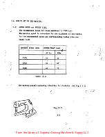
Страница 4: ... is determined by the thickness of the fabric For the recommended speed and corresponding pulley size see chart 1 0 MACHINE SPEED rpm MOTOR PULLY mm 60 Hz 50Hz 2500 40 55 3000 50 65 3500 60 75 CHART 1 0 The machine pulley operating direction is clockwise see Fig 1 0 Fig 1 0 2 0 From the library of Superior Sewing Machine Supply LLC ...

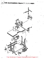
Страница 5: ...3 2 Table stand installation diagram From the library of Superior Sewing Machine Supply LLC ...

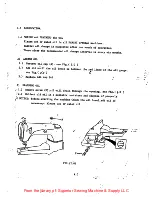
Страница 6: ... 1 Unscrew oil cap A see Fig 2 0 2 Add oU until the oil level is between the red lines of the oil gauge see Fig 2 o 3 Replace oil cap A B DRAINING OIL 1 Remove screw E oU will drain through the opening see Fig 2 0 2 CoUect old oil in asuitable container and dispose of properly NOTICE Before starting the machine CHECK the oil level add oU if necessary Always use SF rated oil FIG 2 0 4 0 From the li...

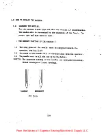
Страница 7: ...THE CORRECT POSITION OF THE NEEDLES 1 The long grove of the needle must be directed towards the operator see Fig 3 0 2 The scarf of the needle will be directed away from the operator 3 The needle must be all the way up in the holder NOTICE The incorrect setting of the needles can cause mis stitching thread breakageand looper breakage V CORRECT V INCORRECT FIG 3 0 5 0 From the library of Superior S...

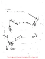
Страница 8: ...4 2 THREADING To thread the machine follow Fig 3 5 JQ NEEDLE THREADING LOOPER THREADING FIG lt5 6 0 From the library of Superior Sewing Machine Supply LLC ...

Страница 9: ...e screw A see Fig 4 0 2 Loosen feed adjusting eccentric E see Fig 4 0 3 Move the eccentric Raise the eccentric for longer stitch length lower the eccentric for smaller stitch length 4 Tighten feed eccentric E 5 Repeat adjustment until proper stitch length is achieved 6 Replace screw A 7 0 From the library of Superior Sewing Machine Supply LLC ...

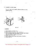
Страница 10: ... be made smaller by rotating screw A In direction D clockwise The differential feed will be made larger by rotating screw A In direction E counter clockwise B The front and rear feed dog must lje set level with each other 1 Loosen screws B and C see Fig 5 0 2 Move Feed dogs to porper level see feed dog height adjustment 3 Tighten screws B and C 8 0 From the library of Superior Sewing Machine Suppl...

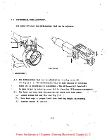
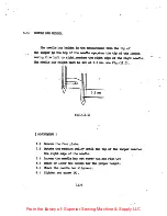
Страница 11: ...in that the needles enter through the center of the holes in the throat plate see Fig 6 0 0 0 ADJUSTMENT FIG 6 0 1 0 Ranove the face plate 2 0 Loosen scr t A see Elg 7 0 3 0 Align the needle bar to the correct position 4 0 Tic ten screw A 4 CHBCK THE NEEDLE BAR HEIOT FIG 7 0 A From the library of Superior Sewing Machine Supply LLC ...

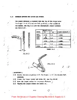
Страница 12: ...OEL Needle Gauge UOOPER DISTANCE B in mm 202R 202591 202D 202S 5 32 4 0 4 6iiia 3 6 4 8 4 3mm 7 32 5 6 4 Qina 1 4 6 0 3 7nn 202WL 1 4 6 0 5 5 TABLS 2 0 FIG 10 0 Mxjusss rr 1 0 Rotate the machine pulley until the locxier is atUtls extreme leift position Loosen the looper rocker set screw C see Fig 10 0 Move the looper rocker to the proper distance Tighten the loc ier rocker set screw C 2 0 3 0 4 0 ...

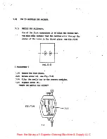
Страница 13: ...e needle bar height must be set at 0 5 nrn see Fig 11 0 i 0 5 mn lii FIG 11 0 MXJUSS iENI 1 Remove the face plate 2 Rotate the machine puU until the tip of the looper readies the right edge of the needle 3 Loosen the needle bar set screw A see Fig 7 0 4 Raise or Icwer the needle bar the premier height 5 Check the needle bar alignment 6 Tighten set screw A 11 0 From the library of Superior Sewing M...

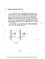
Страница 14: ...eedle eye to the tip of the locper Now turn the hancMieel in the reverse direction OCW until the tip of the looper moving in front of the needle readies the ric t edge of the needle Ohis establishes Msasuransnt B frcm the tc of the needle eye to the tip of the looper When the needle looper synchrcmzation is correct measurements A and B will be the same see Fig 12 0 B V FIG 12 0 12 0 From the libra...

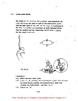
Страница 15: ...needles are travelling on their downward stroke When the needles pass the looper they should deflect 1inhtly off the looper s shoulder FIG 13 0 ADJUSTMENT 1 0 Pemove the back cover plate 2 0 Loosen nut A raising the connecting ball joint vdll decrease the avoid notion lowering the connecting ball joint will increase the avoid motion see Fig 13 0 3 0 Ti ten nut A 13 0 From the library of Superior S...

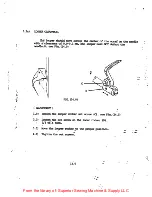
Страница 16: ... the loqper roust NOT defect the needle O see Fig 14 0 FIG 14 0 ADJUSHdENT f 1 0 loosen the looper rocker set screw C see Fig 14 0 2 0 Loosen the set screw on the looer rocker D 1 4 of a turn 3 0 Move the logper rocker the proper position 4 0 Ti ten the set screws 14 0 From the library of Superior Sewing Machine Supply LLC ...

Страница 17: ...it s hi est position Hiis distance should be between 0 8 1 2 nm see Fig 15 0 O Snm 1 2inn FIG 15 0 Mxsuffomns 1 0 Loosen set screw A see Fig 15 0 2 0 lUm the feed adjusting pin B in dicection C will raise the Feed Dog in direction D vdll lower the Peed Dog 3 0 Tighten set screw A 15 0 From the library of Superior Sewing Machine Supply LLC ...

Страница 18: ... 16 0 2 Move the Feed Dog forward and back to the proper position 3 listen set screw A ADJUSTMEZn for DIEFERENTIAL FEED 1 loosen set screws C and D see Fig 16 1 2 Move the front Feed Dog to the proper position 3 Ti ten set screws C and D 4 loosen set screws E and F see Fig 16 1 5 Move the reau Feed Dog to the proper position 6 Tighten set screws E and F Notice The front and rear Feed Dogs jtust no...

Страница 19: ...the needles without deflecting them Hie needle guard hei t is as follows Viien the tip of the looper is at the left edge of the needle the tip of the needle is to be 1 0 ma belcw the top edge of the needle guard 1 0 am 0 FIG 17 0 ADJUSHdENT 1 Loosen set screw A see Fig 17 0 2 Move the needle guard to the proper position 3 Tic ten set screw A When the feed length is adjusted the needle guard positi...

Страница 20: ...released by the forward tip of the take t cam at the time 4 en the tip 6f the rig t needle is level with the center of the looper eye see FIG 18 0 FIG 18 0 ADOUSIMENT V 1 0 Loosen set screws A B see Fig 18 0 2 0 Move the looper thread take n cam to the proper positim 3 0 Tig TSen set screws A B 18 0 From the library of Superior Sewing Machine Supply LLC ...

Страница 21: ...yelets to rards the pperater will increase the amount of lopper draMn by moving the eyelets away from the aerater less Iccper thread will be drawn Mxsuss m FIG 19 0 1 0 Loosen set screws C D see Fig 19 0 2 0 Mo the eyelets in the direction for the pr er amount of looper thread 3 0 Ti ten set screws C D 19 0 From the library of Superior Sewing Machine Supply LLC ...

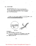
Страница 22: ...st position see Fig 21 0 n FIG 21 0 I ADJUSMENT I 1 Gotater the handviieel in the operation directiQn until the needle lever thread eyelet is at it s hig iest position 2 loosen the needle thread elet set screw G SEE FIG 21 0 3 Msve the needle thread eyelet to the proper position 4 Ti ten the set screw G 21 0 From the library of Superior Sewing Machine Supply LLC ...

Отзывы: