background image

9

Service and Repair Manual

Model 800K

WARNING
LETHAL VOLTAGES PRESENT!!

IMPORTANT

On completion of the assembly, the unit must be flash tested at 4000 volts.

Flash  Test

1. With the breaker completely assembled and with the switch "ON", apply 2000 volts initially and increase rapidly to 4000 volts between the

main casting and one of the pins of the plug on the power supply cord. Apply test to both live and neutral pins.

2. The full voltage of 4000 volts should be maintained without breakdown or flashover for a few seconds.
3. If  the  armature  has  been  tested,  remove  the  carbon  brushes  before  carrying  out  the  test,  (thus  avoiding  overstressing  the  armature

insulation  system).

4. The test voltage must be applied between the main casting and each live pin of the plug in succession.

Running  Test

1. Ensure the unit is switched "ON" before testing. Operate the unit for approx. 10 minutes at half voltage for initial 'bedding in' of the carbon

brushes followed by full operational voltage. Compare readings with Performance Data.

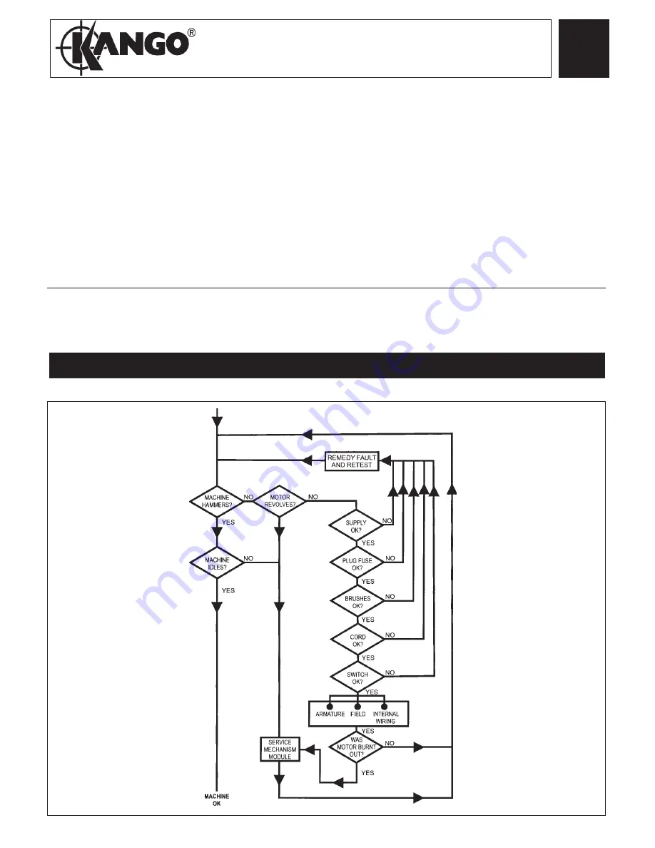
With the aid of the Fault Finding chart (below) the source of any malfunction may be quickly identified and repaired.

FAULT  FINDING

Содержание 800K

Страница 1: ...9800 0334 01 a 800K GB DateCode 0001L2001...

Страница 2: ...o prevent any adverse damage occuring ALL SEALS GASKETS GREASE OR OTHER PARTS DEEMED NECESSARY FOR SERVICINGARE IN THE SERVICE KIT ALLNEEDLE ROLLER BEARINGS SHOULD BE PRESSED WITH THE ROUNDED EDGE ENT...

Страница 3: ...00 230 Volt Armature Kit 1 33 9170 4670 30 230 Volt Field 1 34 9170 4669 10 Carbon Brush 2 36 9170 3252 00 Brush Carrier Assembly 1 39 9170 4669 20 Blade Housing Assembly 1 FIG PART NO DESCRIPTION OF...

Страница 4: ...______________________________ ______________________________________________________________ ________________________________________________________________ _________________________________________...

Страница 5: ...x 70 Skt Hd Cap Screw T 27 4 17 9170 4670 70 Cross Pin 1 18 9170 3258 10 Dowel Pin 1 22 9170 3254 60 8 32 x 3 8 Pan Hd Slt Taptite T 20 1 23 9170 3254 70 M4 x 0 7 x 14 Pan Hd Slt Taptite T 20 4 28 91...

Страница 6: ...AS SHOWN 81 LIGHTLY GREASE INSIDE OF BARREL 81 BEFORE ASSEMBLY 48 73 SMALL OUTSIDE DIAMETER OF SPINDLE 73 IS TO BE LUBRICATED WITH A LIGHT COAT OF GREASE BEFORE ASSEMBLING THE NOSE ASSEMBLY 48 TO THE...

Страница 7: ...ics boat to retain leads as shown Cord to be inserted into clamp trap Cord to extend 1 4 minimum above top of clamp For 120 V only See below for 110 V and 230 V Fast on terminals must be completely co...

Страница 8: ...0 Volts min C Armatuure shaft to commutator 3000 Volts min ELECTRICAL PERFORMANCE TEST READINGS CLUTCH SLIP Measured on disassembly assembly 35 45ft lbs 47 61Nm Non Electrical Test Note On all test re...

Страница 9: ...without breakdown or flashover for a few seconds 3 If the armature has been tested remove the carbon brushes before carrying out the test thus avoiding overstressing the armature insulation system 4...

Страница 10: ...9800 0334 01 a 55 24 3900 Drwg 3 04 02 Atlas Copco Berema AB Sickla Industriv g 1A S 105 23 Nacka Sweden Telephone 46 0 8 743 9600 Fax 46 0 8 743 9650...

Отзывы: