background image

Please take time to read the manual, and familiarise yourself with the controls, and functions of the receiver 
and transmitters before operating or setting up this unit.  


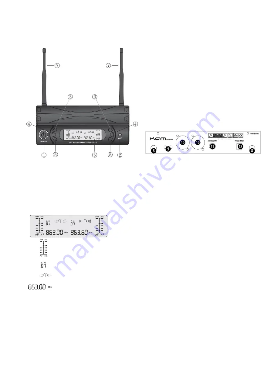
Control and Function list (receiver) 

1.


Power switch 

2.


ACTIR window 

3.


** vol / c 

4.


Channel menu function keys 

5.


** vol / channel - 

6.


LCD display 

7.


Antenna A & B 

8.


Antenna connection 

9.


Squelch control  adjustment 

10.


Balanced output socket A & B 

11.


Mix output socket 

12.


DC  in power input socket 


** Please note. 3&5 buttons have several functions 
To increase the volume of the microphone output press 3 to decrease the volume press the 5 button 


To select one of the 16 channels press the 4 button to select the channel mode, then use 3 or 5 to select the 

desired frequency 


LCD display 


RF intensity and AF intensity indicator


Fix frequency, e.g. 16 channels to choose from. 


Channel A or B 


Use frequency 


Installation of the receiver 

Ensure the aerials on the rear panel A & B are vertical to the receiver.As shown in the picture above. 

Connect the power supply (DC 12-18V) to the mains supply and to the DC input on the rear panel. 


Connection of the audio output 

Mix output:

 Insert one end of the audio cable into UNBALANCED socket on the rear panel and the other end into 

audio amplifier or mixer MIC IN or AUX IN socket.  

Separate balanced output: 

Insert one end of the audio cable into the balanced XLR socket and the other end into 

the amplifier or mixer MIC IN or AUX IN socket. 

Operation of channel B is the same. 

Содержание KWM1960

Страница 1: ...a plc Unit 1 Southfields Road Dunstable Bedfordshire United Kingdom LU6 3EJ Telephone 44 0 1582 690600 Fax 44 0 1582 690400 Email mail lambaplc com Web www lambaplc com If this product is ever no long...

Страница 2: ...d written on the unit The lightning flash symbol inside a triangle is to alert the user to the presence high voltage within the unit s enclosure that may be of sufficient power to constitute a risk of...

Страница 3: ...press the 4 button to select the channel mode then use 3 or 5 to select the desired frequency LCD display RF intensity and AF intensity indicator Fix frequency e g 16 channels to choose from Channel A...

Страница 4: ...esults Turn on the microphone and the LCD display will light up The LCD display will show the frequency of the microphone please ensure this matches the frequency on either CHA or CHB on the receiver...

Страница 5: ...at the channel on the receiver is now locked and set 5 Remove the battery cover 6 Turn the microphone on 7 Hold the microphone in front of the ACTIR window 2 with the IR window above the battery compa...

Страница 6: ...n for the frequencies of these and will set itself to match the transmitters Press the Channel Menu button 4 until scan O is displayed This will deactivate the auto scan mode Press the Channel Menu bu...

Страница 7: ...z 3dB Audio output level 0 400mV Fixed receiver Power supply DC17V 300MA Consume power 4w Signal noise ratio More than 90dB Image spurious rejection More than 80dB Border upon channel rejection More t...

Отзывы: