Kair KHRV150/12RH Скачать руководство пользователя страница 7

Location of the Transformer/Humidity Sensor unit

Page

6

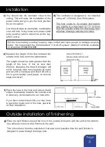
The  Transformer  /  Humidity  sensor  unit
may be mounted on the wall or ceiling.

Position the transformer / humidity unit
at least 6” (150mm) from a corner to allow
correct airflow over the humidity sensor.
Also,  ensure  the  humidity  sensor  unit  is
not directly in the stream of the fresh air
coming  in  from  the  fan  unit,  as  this  will
result in false sensing.

An ideal location is on the same wall, or
one immediately adjacent which is in the
stream  of  the  stale  /  damp  air  being
drawn into the side vents of the fan
assembly.

o)

Note: This part must not be mounted in
the interior of a bath tub or shower
basin and must be positioned out of
reach of a person using a fixed bath or
shower. It should be also positioned
away form any source of water spray.

Wiring:

IF IN DOUBT CONSULT A QUALIFIED ELECTRICIAN

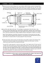
Decide how you are going to run the wires from the transformer to the fan unit. All wiring must
be in accordance with current IEE wiring regulations.

A 5 amp two core power cable is required to connect the fan assembly to the remote control.
A two core, 3 amp supply is required on the input mains connection.
An earth connection is not required.

Pass the input and output wires through the cable hole in the base plate of the remote control
and fasten it in position. (

SEE DIAGRAM ON PAGE 2)

To comply with electrical safety regulations both input and output leads must be clamped to
the unit using the saddle clamps provided.

Mains wiring for remote control and transformer:

Red or Brown wire  


to live terminal

Black or Grey wire  


to neutral terminal

Do not apply power to the transformer yet!

No  earth  is  required  to  the  ventilator  in  accordance  with  IEE  wiring  regulations  for  SELV
circuits.

All wiring must be 1mm Minimum, fixing securely to comply with IEE wiring regulations. If in
doubt consult a qualified electrician.

m)

n)

Содержание KHRV150/12RH

Страница 1: ...rmer Humidity Sensor unit 7 Transformer Humidity Sensor unit Wiring 8 Light Level Sensor 8 9 10 Maintenance 10 Registration 11 Warranty www kair co uk What am I Included items Description Qty Through...

Страница 2: ...mer Humidity sensor unit The humidistat monitors the humidity in the room and automatically switches the ventilator from continuous trickle speed to boost if the humidity exceeds the set point e g whe...

Страница 3: ...sitioned a minimum of 500mm away from any gas flue to avoid back flow of gases Indicate the position of the core drill hole on the inside wall If possible mark its position on the outside wall too See...

Страница 4: ...4 036 e Measure the length of the hole between the outside brick face and inner plasterwork The length should be 4mm greater than the length of the hole X but no less than 254mm otherwise the Heat Exc...

Страница 5: ...finisher in place Ensure that the finisher does not fall v Now manipulate the finisher to expand it outwards and increase its internal diameter as much as possible This will assist the re entry of the...

Страница 6: ...rom the cable entry hole top left upwards to the ceiling or in the direction you have determined for the transformer or remote control Fit screw plugs into the screw holes l Fit the wall plate onto th...

Страница 7: ...ELECTRICIAN Decide how you are going to run the wires from the transformer to the fan unit All wiring must be in accordance with current IEE wiring regulations A 5 amp two core power cable is require...

Страница 8: ...suring that the switch is in the TRICKLE position The LED shown on page 2 being extinguished confirms this After the system has run for some time check the fan unit switches to boost by directing stea...

Страница 9: ...it to perform at its maximum efficiency to control the humidity level within the room in which it is fitted Proper maintenance will also prevent the internal fans switching to boost mode more frequent...

Страница 10: ...e main fan unit away from the wall a small distance only at this stage i e 510mm This will allow the front filter covers to be removed without losing dropping or damaging them if required although it...

Страница 11: ...ss if the fan unit and wall plate are secured 17 Once the fan has been re instated in the wall and the mains is switched on the filters will continue to clean the incoming air supply to prolong the li...

Страница 12: ...re that it is adequately packed and accompanied by a letter clearly marked Guarantee Claim stating the nature of the fault and providing evidence of date and source of purchase The guarantee is offere...

Отзывы: