background image

1 3.

GRINDING OF DRILLS

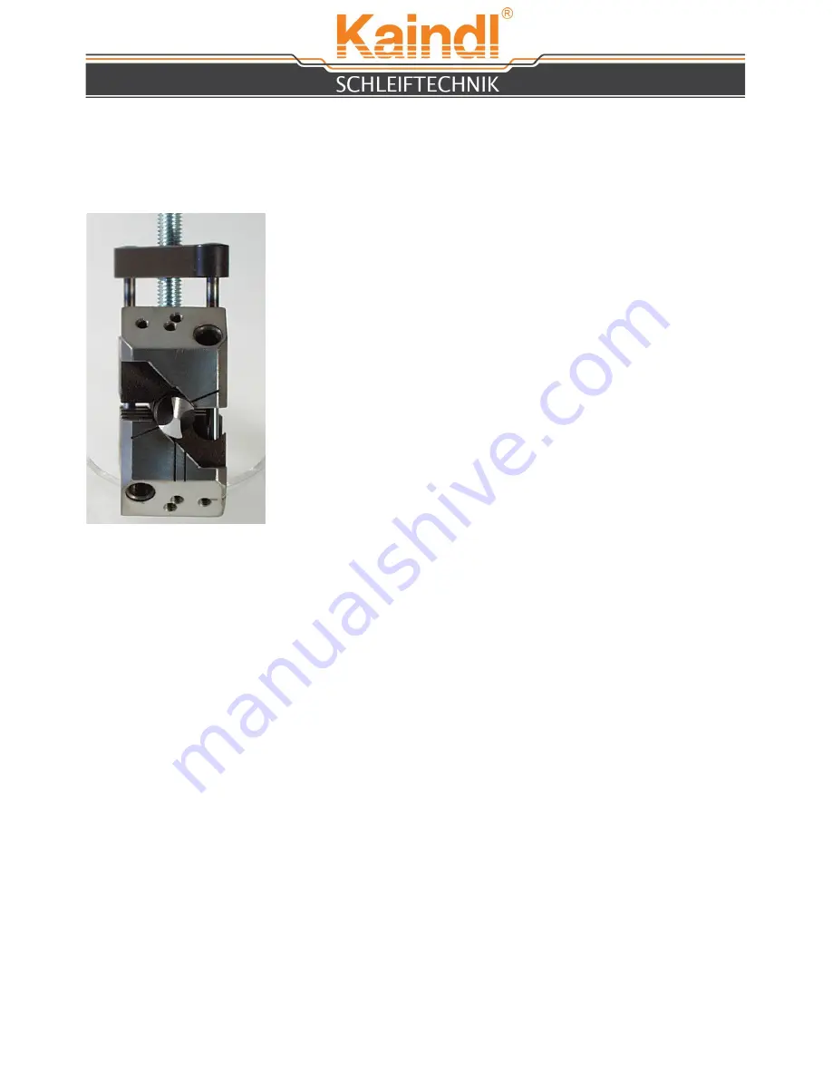
PLACING AND ADJUSTMENT OF DRILLS

The reversing prism comprised a range of 2-20 mm. The

insertion and alignment of the drill is achieved in the most

simple manner conceivable. Open the prism by means of the

knurled head screw, provided for this purpose. Now insert the

drill to be ground inside the prism.
Keep the drill projecting about 1 5 - 20 mm beyond the prism

edge. The prism jaws are pressed together by a slight turn of

the knurled screw. The thus inserted drill is held tight in this

position, but it can still be turned easily as this is important for

the alignment. Now it is only neccessary to align the cutting

edge of the drill in parallel to the two indicated marks

(

Mark A

= right-hand drills;

Mark B

= left-hand drills).

The prism is to be tightened by hand only a hereafter, the

grinding operation can be started.

1 2

In order to work always in conformity with the properties of the material, you have the

opportunity no adjust every top angle that is imaginable.
The common top angle are 11 8°, 1 30° and 1 80° degrees.

The angles are solidly marked on the prism slide. They can easily adjusted by opening

the clamping lever (see picture on page 5, No. 6) and by moving the prism rest.

1 4.

ADJUSTMENT OF THE TOP ANGLE

Deviating from this basic adjustment, you can change your relief angle depending on the

material to be drilled.
You want a higher clearance angle - a higher cutting capacity, then revolve the drill

slightly to the left (shorter graduation mark on the prism). If you want less relief - a lower

cutting capacity, then revolve the drill slightly to the right (longer graduation mark on the

drill). You will thus obtain the correct cutting edge and angle for every kind of material.
In case of a broken drill, having no cutting edge for adjustment, grind the drill to get a

truncated end. Align the cutting corners as closely as possible to the adjustment marks

and regrind the drill until a new cutting edge apears. Thereafter the adjustment is to be

carried out as before.

B

B

A

Содержание BSG 20/2

Страница 1: ...NG MACHINE BSG 20 2 Original manual Please keep for further use Kaindl Schleiftechnik REILING GmbH Remchinger Str 4 D 75203 K nigsbach Stein Germany Tel 49 7232 4001 0 Fax 49 7232 4001 30 Internet www...

Страница 2: ...e 8 Set up 8 Mounting and dressing the grinding wheel before first operation 9 Dressing of the grinding wheel 10 Change of the grinding wheel 11 Operation Grinding of drills 12 Adjustment of top angle...

Страница 3: ...EC directive EMV 2004 108 EC Applied harmonised norms EN ISO 12100 1 and EN ISO 12100 2 EN ISO 13857 EN ISO 13732 1 EN 61029 1 EN 60204 Part 1 EN 61000 6 1 EN 61000 6 2 EN 61000 6 3 EN 61000 6 4 Chan...

Страница 4: ...s not destined for and is regarded as a matter of adverse use The directed use includes also reading the operation manual as well as keeping all containing directions of use expecially the safety info...

Страница 5: ...ed screw for prism fixation 6 Clamping lever for top angle adjustment 7 Hexagon screw for motor angle fixation 8 Knurled nut with scale for motor feed 9 Knurled nut with scale for drill feed 10 Revers...

Страница 6: ...ll wear parts make the Kaindl grinding machine BSG 20 2 to an indispensable auxiliary for many years in your company 6 4 TECHNICAL DATA Dimension L x W x H 290 x 220 x 250 mm Weight net 13 5 Kg Travel...

Страница 7: ...ary steps are taken It is the duty of taking care by user to control these steps The user has to take care that Sound check mounting and dressing of the wheel before the first start see page 9 the BSG...

Страница 8: ...or life and health of persons Danger This icon points that there exists a danger for machines material and environment Attention 9 MOVING TO ANOTHER PLACE Only with disconnected plug Grap the drill gr...

Страница 9: ...DING WHEEL BEFORE THE FIRST OPERATION After you have mounted the grinding wheel support place the wheel on the motor spindle see page 11 Change of grinding wheel After the grinding wheel is placed cor...

Страница 10: ...ring hole of the prism rest Move the motor feed with the knurled nut slowly towards the turning grinding wheel When the diamond pin touches the grinding wheel then move the motor feed back and furth D...

Страница 11: ...he threaded pin is in the notch of the motor spindle picture 3 Now fix the screw in the center of the wheel support with the allen key SW 4 0 and mount the grinding wheel cover in opposite sequeence T...

Страница 12: ...ties of the material you have the opportunity no adjust every top angle that is imaginable The common top angle are 118 130 and 180 degrees The angles are solidly marked on the prism slide They can ea...

Страница 13: ...hout any alteration of the position of the drill feed carriage The other side is ground until no more spark are visisble ATTENTION In order to prevent temper of anneal please always work with low feed...

Страница 14: ...p work has been completed switch on the motor and start working ad described in the chapter Grinding of drills For milling cutters the prism is fixed with the knurled screw in the lower screw hole pla...

Страница 15: ...the prism with the knurled screw in hole C Use the upper boring on the prism support Loosen the clamping lever and move the prism support to 90 By use of the prism and motor feed thin the web of the...

Страница 16: ...Open the clamping lever and turn the prism support to 150 Move with the motor feed to the left till you touch the cross cutting edge of the twist drill by the right edge of the grinding wheel Dive sl...

Страница 17: ...t switch 15422 Grinding wheel support complete without grinding wheel Only use original Kaindl spare parts 20 SPARE PART LIST 21 MAINTENANCE The drill grinder BSG 20 2 should be cleaned from grinding...

Страница 18: ...uded from any warranty are Wear parts due to operating conditions Transport damage Inappropriate use of the machine Damages by use of force Damages and consequential damages by violation of duty for t...

Отзывы: