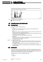
Fig. 4 Machine layout
1
Inlet valve
2
Minimum pressure/check valve
3
Drive motor
4
Oil filter
5
Airend
6
Control cabinet
7
Oil separator tank
8
Air filter
9
Oil/air cooler
Ambient air is cleaned as it is drawn in through the filter
8
.
The air is then compressed in the airend
5
.
The airend is driven by an electric motor
3
.
Cooling oil is injected into the airend. It lubricates moving parts and forms a seal between the rotors
themselves and between them and the airend casing. This direct cooling in the compression chamber
ensures a very low airend discharge temperature.
Cooling oil recovered from the compressed air in the oil separator tank
7
gives up its heat in the oil
cooler
9
. The oil then flows through the oil filter
4
and back to the point of injection. Pressure within
the machine keeps the oil circulating. A separate pump is not necessary. A thermostatic valve main‐
tains optimum cooling oil temperature.
Compressed air, freed of cooling oil in the oil separator tank
7
, flows through the minimum pressure/
check valve
2
into the air cooler
9
. The minimum pressure/check valve ensures that there is always
a minimum internal air pressure sufficient to maintain cooling oil circulation in the machine.
The air cooler brings down the compressed air temperature of only 5 to 10 K above ambient. Most of
the moisture carried in the air is removed during this cooling process.
4.3 Floating relay contacts
Floating relay contacts are provided for the transfer of signals, messages.
Information on location, loading capacity and type of message or signal is found in the electrical
diagram.
If the floating relay contacts are connected to an external voltage source, voltage may be
present even when the machine is isolated from the power supply.
4
Design and Function
4.3
Floating relay contacts
26
Service Manual Screw Compressor
BSD
9_5708 08 USE
Содержание BSD 40
Страница 1: ...Service Manual Screw Compressor BSD 9_5708 08 USE ...
Страница 2: ...Original instructions KKW SBSD 1 02 en 01 SBA SCHRAUBEN SC KKW SSC 1 04 01 ...
Страница 6: ...Contents iv Service Manual Screw Compressor BSD 9_5708 08 USE ...
Страница 8: ...List of Illustrations vi Service Manual Screw Compressor BSD 9_5708 08 USE ...
Страница 10: ...List of Tables viii Service Manual Screw Compressor BSD 9_5708 08 USE ...
Страница 108: ...13 Annex 13 1 Pipeline and instrument flow diagram P I diagram 98 Service Manual Screw Compressor BSD 9_5708 08 USE ...
Страница 109: ...13 Annex 13 1 Pipeline and instrument flow diagram P I diagram 9_5708 08 USE Service Manual Screw Compressor BSD 99 ...
Страница 110: ...13 Annex 13 1 Pipeline and instrument flow diagram P I diagram 100 Service Manual Screw Compressor BSD 9_5708 08 USE ...
Страница 111: ...13 Annex 13 1 Pipeline and instrument flow diagram P I diagram 9_5708 08 USE Service Manual Screw Compressor BSD 101 ...
Страница 112: ...13 Annex 13 1 Pipeline and instrument flow diagram P I diagram 102 Service Manual Screw Compressor BSD 9_5708 08 USE ...
Страница 119: ...13 3 Dimensional Drawing 13 Annex 13 3 Dimensional Drawing 9_5708 08 USE Service Manual Screw Compressor BSD 109 ...
Страница 120: ...13 Annex 13 3 Dimensional Drawing 110 Service Manual Screw Compressor BSD 9_5708 08 USE ...
Страница 121: ...13 Annex 13 3 Dimensional Drawing 9_5708 08 USE Service Manual Screw Compressor BSD 111 ...
Страница 122: ...13 Annex 13 3 Dimensional Drawing 112 Service Manual Screw Compressor BSD 9_5708 08 USE ...
Страница 123: ...13 4 Electrical Diagram 13 Annex 13 4 Electrical Diagram 9_5708 08 USE Service Manual Screw Compressor BSD 113 ...
Страница 124: ...13 Annex 13 4 Electrical Diagram 114 Service Manual Screw Compressor BSD 9_5708 08 USE ...
Страница 125: ...13 Annex 13 4 Electrical Diagram 9_5708 08 USE Service Manual Screw Compressor BSD 115 ...
Страница 126: ...13 Annex 13 4 Electrical Diagram 116 Service Manual Screw Compressor BSD 9_5708 08 USE ...
Страница 127: ...13 Annex 13 4 Electrical Diagram 9_5708 08 USE Service Manual Screw Compressor BSD 117 ...
Страница 128: ...13 Annex 13 4 Electrical Diagram 118 Service Manual Screw Compressor BSD 9_5708 08 USE ...
Страница 129: ...13 Annex 13 4 Electrical Diagram 9_5708 08 USE Service Manual Screw Compressor BSD 119 ...
Страница 130: ...13 Annex 13 4 Electrical Diagram 120 Service Manual Screw Compressor BSD 9_5708 08 USE ...
Страница 131: ...13 Annex 13 4 Electrical Diagram 9_5708 08 USE Service Manual Screw Compressor BSD 121 ...
Страница 132: ...13 Annex 13 4 Electrical Diagram 122 Service Manual Screw Compressor BSD 9_5708 08 USE ...
Страница 133: ...13 Annex 13 4 Electrical Diagram 9_5708 08 USE Service Manual Screw Compressor BSD 123 ...
Страница 134: ...13 Annex 13 4 Electrical Diagram 124 Service Manual Screw Compressor BSD 9_5708 08 USE ...
Страница 135: ...13 Annex 13 4 Electrical Diagram 9_5708 08 USE Service Manual Screw Compressor BSD 125 ...
Страница 136: ...13 Annex 13 4 Electrical Diagram 126 Service Manual Screw Compressor BSD 9_5708 08 USE ...
Страница 137: ...13 Annex 13 4 Electrical Diagram 9_5708 08 USE Service Manual Screw Compressor BSD 127 ...
Страница 138: ...13 Annex 13 4 Electrical Diagram 128 Service Manual Screw Compressor BSD 9_5708 08 USE ...
Страница 139: ...13 Annex 13 4 Electrical Diagram 9_5708 08 USE Service Manual Screw Compressor BSD 129 ...
Страница 140: ...13 Annex 13 4 Electrical Diagram 130 Service Manual Screw Compressor BSD 9_5708 08 USE ...
Страница 141: ...13 Annex 13 4 Electrical Diagram 9_5708 08 USE Service Manual Screw Compressor BSD 131 ...
Страница 142: ...13 Annex 13 4 Electrical Diagram 132 Service Manual Screw Compressor BSD 9_5708 08 USE ...
Страница 143: ...13 Annex 13 4 Electrical Diagram 9_5708 08 USE Service Manual Screw Compressor BSD 133 ...
Страница 144: ...13 Annex 13 4 Electrical Diagram 134 Service Manual Screw Compressor BSD 9_5708 08 USE ...
Страница 145: ...13 Annex 13 4 Electrical Diagram 9_5708 08 USE Service Manual Screw Compressor BSD 135 ...
Страница 146: ...13 Annex 13 4 Electrical Diagram 136 Service Manual Screw Compressor BSD 9_5708 08 USE ...

