background image


Service Manual 

Screw Compressor  

BSD  


9_5708 08 USE

Содержание BSD 40

Страница 1: ...Service Manual Screw Compressor BSD 9_5708 08 USE ...

Страница 2: ...Original instructions KKW SBSD 1 02 en 01 SBA SCHRAUBEN SC KKW SSC 1 04 01 ...

Страница 3: ...esign data 11 2 15 2 Cooling water quality 12 2 16 Heat recovery 13 2 16 1 Prepared for external heat recovery 13 2 16 2 Internal heat recovery 13 3 Safety and Responsibility 3 1 Basic Information 16 3 2 Specified use 16 3 3 Improper Use 16 3 4 User s Responsibilities 16 3 4 1 Observe statutory and universally accepted regulations 16 3 4 2 Qualified personnel 17 3 4 3 Adhere to Inspection Schedule...

Страница 4: ...ptions 39 6 5 1 Anchoring the machine 39 6 5 2 Connecting the cooling water 39 6 5 3 Connecting the heat recovery system 40 7 Initial Start up 7 1 Safety 42 7 2 To be noted before commissioning 42 7 3 Checking installation and operating conditions 43 7 4 Setting the overload protection cut out 44 7 5 Setting the motor overload protection switch 44 7 6 Filling cooling oil into the airend 44 7 7 Che...

Страница 5: ...ing the machine depressurizing 74 10 15 Topping up the Cooling Oil 76 10 15 1 Venting the Machine depressurizing 76 10 15 2 Top up with cooling oil and test run 77 10 16 Changing the cooling oil 78 10 17 Changing the Oil Filter 83 10 18 Changing the Oil Separator Cartridge 84 10 19 Document maintenance and service work 87 11 Spares Operating Materials Service 11 1 Note the nameplate 88 11 2 Orderi...

Страница 6: ...Contents iv Service Manual Screw Compressor BSD 9_5708 08 USE ...

Страница 7: ...remote control center 50 Fig 21 Switching on and off with the clock 51 Fig 22 Acknowledging messages 52 Fig 23 Cooling air filter mat 66 Fig 24 Control cabinet ventilation grill 67 Fig 25 Cleaning the cooler 68 Fig 26 Air filter maintenance 70 Fig 27 Drive motor maintenance 71 Fig 28 Checking the coupling 72 Fig 29 Checking the cooling oil level 74 Fig 30 Venting the machine 75 Fig 31 Topping up t...

Страница 8: ...List of Illustrations vi Service Manual Screw Compressor BSD 9_5708 08 USE ...

Страница 9: ...ion option K2 12 Tab 27 Cooling water quality 12 Tab 28 Heat capacity option W1 13 Tab 29 Water quality specification 14 Tab 30 Heat exchanger specification option W2 W3 14 Tab 31 Heat capacity option W2 W3 15 Tab 32 Flow rate pressure loss option W2 15 Tab 33 Flow rate pressure loss option W3 15 Tab 34 Danger Areas 21 Tab 35 Safety Signs 22 Tab 36 Energy efficient control modes 30 Tab 37 Operatin...

Страница 10: ...List of Tables viii Service Manual Screw Compressor BSD 9_5708 08 USE ...

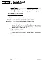
Страница 11: ...Make sure you give the data from the nameplate when ordering documents 1 3 Copyright This service manual is copyright protected Queries regarding use or duplication of the documentation should be referred to KAESER Correct use of information will be fully supported 1 4 Symbols and Identification 1 4 1 Warnings Warning notices indicate three levels of danger signified by the signal word DANGER WARN...

Страница 12: ...us situations This bullet is is placed by lists of actions comprising one stage of a task In lists of actions with several stages the sequence of actions is numbered Information that refers to only one option is marked with an indicator e g H1 means that this section is only valid for machines with adjustable machine mountings Option indicators used in this service manual are explained in chapter ...

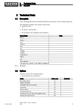
Страница 13: ...psig cfm Voltage Hz RPM Package FLA Phase HP Wiring Diagram FOR SERVICE REFER TO EQUIPMENT NUMBER Tab 2 Nameplate 2 2 Options The table contains a list of possible options Enter options here as a reference Option Option code Available Modulating control C1 SIGMA CONTROL C3 Adjustable machine mountings H1 Air cooling K1 Water cooling K2 Cooling air filter mat K3 Transformer power supply for refrige...

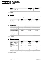
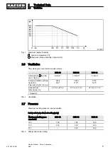
Страница 14: ... tion F 167 200 167 200 167 200 Maximum airend dis charge temp automatic shut down F 230 230 230 Tab 5 Temperature 2 5 Ambient Conditions BSD 40 BSD 50 BSD 60 Maximum elevation ft 3000 3000 3000 Permissible ambient tem perature F 40 115 40 115 40 115 Cooling air temperature F 40 115 40 115 40 115 Inlet air temperature F 40 115 40 115 40 115 Maximum relative humidi ty of inlet air see figure 1 see ...

Страница 15: ...st fan Flow rate cfm at 0 4 in wc 6474 942 7946 1177 9712 1471 Exhaust duct Dimensions in 27 1 2 x 27 1 2 27 1 2 x 27 1 2 27 1 2 x 27 1 2 Option K2 Tab 7 Ventilation 2 7 Pressure Maximum working pressure see nameplate Safety relief valve blow off setting psig Maximum working pres sure psig BSD 40 BSD 50 BSD 60 125 155 155 155 175 230 230 230 217 232 232 Tab 8 Safety relief valve setting 2 Technica...

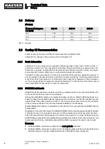
Страница 16: ...stored in a protected location to prevent contamination Do not re use drums flush and send to reconditioner Although the KAESER synthetic is not highly flammable it will burn While KAESER synthetic com pressor cooling oil is less flammable than equal viscosity mineral oils it cannot be classified as a fire resistant fluid It has a flash point above 460 F Since the user has total control over the c...

Страница 17: ...food contact may occur with the discharge air This lubricant meets the requirements of the FDA Regulation 21 CFR 178 3570 and is USDA H 1 approved and NSF certified FG 460 is approved for canning food packing meat and poultry processing and other applications where incidental food contact may occur 2 10 Cooling oil charge The required cooling oil charge depends on the optional heat recovery system...

Страница 18: ... 1 6 Tab 14 Cooling oil charge Option W3 2 11 Motors and Power 2 11 1 Drive motor BSD 40 BSD 50 BSD 60 Rated power hp 40 50 60 Rated speed rpm 3565 3565 3570 Enclosure protection TEFC TEFC TEFC Motor bearing greasing in terval h 2000 2000 2000 Grease requirement each bearing g Transfer data from the motor nameplate to the table for reference purposes h operating hours Tab 15 Drive motor 2 11 2 Opt...

Страница 19: ...stance 1 m BSD 40 BSD 50 BSD 60 Sound pressure lev el dB A 68 69 71 Tab 18 Sound pressure level 2 13 Power Supply Basic requirements The machine is designed for an electrical supply according to National Electric Code NEC NEC 670 particularly NFPA 79 edition 2007 section 4 3 In the absence of any user specified alternatives the limits given in these standards must be adhered to Consult manufacture...

Страница 20: ... the cross section should be checked and adjusted according to 2008 NEC 110 14 220 3 310 15 Table 310 16 430 6 430 22 430 24 and other local codes Dual element time delay fuses are selected according to 2008 NEC 240 6 430 52and tables 430 52 430 248 and 430 250 We strongly suggest using a separate copper conductor for the equipment GROUNDING NEC Ta ble 250 122 will point out the minimum size howev...

Страница 21: ...tion details 460V 3 60Hz Rated power supply 575V 10 3 ph 60Hz BSD 40 BSD 50 BSD 60 Pre fuse A 60 80 70 90 Supply 4x AWG4 4x AWG3 4x AWG1 Consumption A 43 54 66 75 C Tab 23 Supply 575V 3 60Hz 2 15 Option K2 Water cooling Further information The dimensional drawing in chapter 13 3 gives the flow direction size and position of the connection ports 2 15 1 Design data Cooling water temperature rise 20 ...

Страница 22: ...oler specification option K2 2 15 2 Cooling water quality Oil may contaminate the cooling water if a leak occurs A special heat exchanger must be used for heating drinking water The specific heat capacity and required flow rate of the cooling water changes if antifreeze is added Consult authorized KAESER Service representative to ensure optimum cooling system performance It is imperative that meas...

Страница 23: ... 2 16 1 Option W1 Prepared for external heat recovery The quality of the heat transfer medium and its required flow rate depend on the type of heat exchanger used Maximum permissible pressure loss in the cooling oil circuit 8 7 psi Maximum heat capacity available BSD 40 BSD 50 BSD 60 kW 27 0 33 3 40 8 MJ h 97 120 147 kcal h 23216 28616 35082 With the combination valve set to open at 176 F Tab 28 H...

Страница 24: ... mg l 0 2 Dissolved nitrate NO3 mg l 100 Hydrogen sulphide H2S mg l 0 05 Free aggressive carbon dioxide CO2 mg l 5 Glycol 50 Solids particle size mm 0 1 Algae Not permitted Tab 29 Water quality specification Heat exchanger specification BSD 40 BSD 50 BSD 60 Material 1 4401 1 4401 1 4401 Braze Copper Cu Copper Cu Copper Cu Maximum working pres sure psig heat transfer medium 145 145 145 Maximum perm...

Страница 25: ... F to 158 F equivalent to ΔT 45F BSD 40 BSD 50 BSD 60 Flow rate gpm 4 0 5 3 6 2 Pressure drop psi 2 9 3 6 3 6 Tab 32 Flow rate pressure loss option W2 Flow rate for heating from 59 F to 158 F equivalent to ΔT 99F BSD 40 BSD 50 BSD 60 Flow rate gpm 1 8 2 2 2 6 Pressure drop psig 1 5 2 2 2 2 Tab 33 Flow rate pressure loss option W3 2 Technical Data 2 16 Heat recovery 9_5708 08 USE Service Manual Scr...

Страница 26: ...service manual Operate the machine only within its performance limits and under the permitted ambient condi tions Do not use compressed air for breathing purposes unless it is specifically treated Do not use compressed for any application that will bring it into direct contact with food products unless it is specifically treated 3 3 Improper Use Never direct compressed air at persons or animals Co...

Страница 27: ...le dangers of electrical and compressed air devices and take appropriate measures to safeguard persons and property have received adequate training and authorization for the safe installation and maintenance on this equipment Additional qualifications for compressors with refrigeration dryers fully conversant with the safety concepts and regulations concerning refrigeration devices must be able to...

Страница 28: ...ure Close shut off valves or otherwise isolate the machine from the compressed air system to ensure that no compressed air can flow back into the machine Vent all pressurized components and chambers completely Do not carry out welding heat treatment or mechanical modifications to pressurized components e g pipes and vessels as this influences the component s resistance to pressure The safety of th...

Страница 29: ...g with lubricants and chemical substances Avoid contact with skin and eyes Do not inhale oil mist or vapor Do not eat or drink while handling cooling and lubricating fluids Keep suitable fire extinguishing agents ready for use Use only KAESER approved operating materials Unsuitable spare parts Use only spare parts approved by the manufacturer for use in this machine Unsuitable spare parts compromi...

Страница 30: ...rature and humidity clean inlet air with no damaging contaminants inlet air free of explosive or chemically unstable gases or vapors inlet air free of acid alkaline forming substances particularly ammonia chlorine or hydrogen sulfide Do not position the machine in warm exhaust air from other machines Ensure accessibility so that all work on the machine can be carried out without danger or hin dran...

Страница 31: ...aintenance personnel Tab 34 Danger Areas 3 6 Safety Devices Various safety devices ensure safe working with the machine Do not change bypass or disable safety devices Check safety devices for correct function regularly Do not remove or obliterate labels and notices Ensure that labels and notices are clearly legible Further information More information on safety devices is contained in chapter 4 se...

Страница 32: ...Contamination of food can result from using untreated compressed air for food proc essing Never breathe untreated compressed air Air from this compressor must meet OSHA 29CFR1910 134 and FDA 21CFR178 3570 standards if used for breathing or food processing Use proper compressed air treatment 13 Hot surface can cause burns Let the machine cool down Wear long sleeved garments not synthetics such as p...

Страница 33: ...7 Risk of electric shock If the interrupter has tripped current carrying components of the controller should be examined and replaced if damaged to reduce the risk of fire or electric shock 28 Risk of electric shock To maintain overcurrent short circuit and ground fault protection the manufacturer s instructions for setting the interrupter must be followed to reduce the risk of fire or electric sh...

Страница 34: ...e the obligation lies with the user to determine its suitability for his specific application In addition we accept no warranty obligation for the use of unsuitable parts or operating materials unauthorized modifications incorrect maintenance incorrect repair Correct maintenance and repair includes the use of original spare parts and operating materials Obtain confirmation from KAESER that your sp...

Страница 35: ... uses Walking on standing or sitting on As resting place or storage of any kind of load Safe and reliable operation is only assured with the enclosure closed Access doors are hinged to swing open and removable panels can be lifted off Latches are released by a key supplied with the machine 4 2 Functional Description of the Machine Functional description using an air cooled machine as an example 4 ...

Страница 36: ...eparate pump is not necessary A thermostatic valve main tains optimum cooling oil temperature Compressed air freed of cooling oil in the oil separator tank 7 flows through the minimum pressure check valve 2 into the air cooler 9 The minimum pressure check valve ensures that there is always a minimum internal air pressure sufficient to maintain cooling oil circulation in the machine The air cooler ...

Страница 37: ...t filters the cooling air and keeps the cooler surface clean Fig 6 Cooling air filter mat option K3 1 Cooling air filter mat 4 4 3 Option K2 Water cooling Plate heat exchangers in stainless steel are used for water cooled machines An additional container supplements the cooling oil circuit This additional container is omitted on machines with heat recovery 4 Design and Function 4 4 Options 9_5708 ...

Страница 38: ... the machine Prepared for external heat recovery Connections are provided for an external system to recover surplus heat The thermostatic valve does not function when the machine is delivered The necessary working element must be installed when installing the heat recovery system If necessary the working element in the combination valve can be exchanged for one with higher opening temperature The ...

Страница 39: ...eparator from the distribution network The oil separator tank is vented The compressor motor is stopped MODULATING CONTROL With the help of a control valve the proportional controller the degree of opening of the inlet valve is steplessly varied in response to the air demand The airend delivers compressed air to the distribution network The load and power consumption of the drive motor rises and f...

Страница 40: ...topped QUADRO In the QUADRO mode the controller operates as in the DUAL mode during periods of high air demand by switching between LOAD and IDLE but during periods of low air demand it switches directly to STANDSTILL In this control mode the controller requires two specified times The running time and the idle stand still time The shorter these time period settings the sooner and more frequently ...

Страница 41: ...essure It is preset at the factory Enclosures and guards for moving parts and electrical connections These protect against accidental contact 4 7 SIGMA CONTROL Keys and Indicators Fig 9 Keys Item Description Function 1 ON Switches on the machine The programmed operating mode is active 2 OFF Switches the machine off 3 Clock Switches clock control on and off 4 Remote control Switches remote control ...

Страница 42: ...larms and warning messages Resets the event memory when permitted Tab 38 Keys Fig 10 Indicators Item Description Function 12 Display field Alphanumeric display with 4 lines 13 Alarm Flashes red when an alarm occurs Lights continuously when acknowledged 14 Communication Lights red if communication via the Profibus interface is interrupted 15 Warning Flashes yellow for maintenance work due warning m...

Страница 43: ... pressed 19 Machine ON Lights green when the machine switched on 20 Clock The LED lights when the machine is in clock control 21 Remote control The LED lights when the machine is in remote control Tab 39 Indicators 4 Design and Function 4 7 SIGMA CONTROL Keys and Indicators 9_5708 08 USE Service Manual Screw Compressor BSD 33 ...

Страница 44: ...ine forming substances particularly ammonia chlorine or hydrogen sulfide Ensure sufficient and suitable lighting such that the display can be read and work carried out comfortably and safely Keep suitable fire extinguishing agents ready for use 5 2 Installation conditions 5 2 1 Determining location and clearances The machine is intended for installation in an appropriate machine room Information o...

Страница 45: ... ventilation If the ventilation is insufficient a partial vacuum can be created in the room Ensure that the volume of air flowing into the machine room is at least equivalent to that being removed from it by the machine and exhaust fan Make sure that the machine and exhaust fan can only operate when the inlet aperture is actually open Keep the inlet and exhaust apertures free of obstructions so th...

Страница 46: ...ducts can be found in chapter 13 3 5 3 Using the Compressor to Supply A Compressed Air System When the machine is connected to a compressed air system the system operating pressure must not exceed 232 psig Initial filling of a fully vented air network generally creates a very high rate of flow through air treatment devices These conditions are detrimental to correct treatment Air quality suffers T...

Страница 47: ... otherwise isolate the machine from the compressed air system to ensure that no compressed air can flow back into the machine 2 Vent all pressurized components and chambers completely 3 Check all machine hose connectors with a handheld pressure gauge to ensure that all read zero 4 Do not open or dismantle such valves Working on the drive 1 Switch off and lock out the supply disconnecting device an...

Страница 48: ...ectricity supplier must be observed 3 Test the overload protection cut out to ensure that the time it takes to disconnect in response to a fault is within the permitted limit 4 Use supply conductors and fuses in accordance with local regulations 5 The user must provide the machine with a lockable supply disconnecting device This could be for example a switch disconnector with fuses If a circuit br...

Страница 49: ...according to the difference in temperature between the supply and the return water Individual machines may not receive an adequate flow under this system Breakdowns are the result KAESER can advise on how to ensure the cooling water supply via suitable control valves Fig 13 Connecting the cooling water A Cooling water outlet B Cooling water inlet 10 Shut off valve 12 Connection port with plug 17 P...

Страница 50: ...ratures of the heat transfer medium as it can cause condensation If required contactKAESER for suitable insulation measures WARNING Cooling oil in the heat receiving medium Oil may contaminate the medium if a leak occurs Do not use the heat receiving medium as drinking water Install the heat recovery system in accordance with the following specifications Further information The dimensional drawing...

Страница 51: ... ports 12 for maintenance and venting Pressure relief valve 17 to prevent build up of excessive pressure Blow off pressure and capacity are governed by the user s installation design The technical specification of the heat exchanger must be taken into consideration 2 Connect the supply lines and fittings 3 Open the shut off valve 10 at the inlet A 4 Slowly open the shut off valve 10 at the inlet B...

Страница 52: ...oating relay contacts Working on pressure systems 1 Close shut off valves or otherwise isolate the machine from the compressed air system to ensure that no compressed air can flow back into the machine 2 Vent all pressurized components and chambers completely 3 Check all machine hose connectors with a handheld pressure gauge to ensure that all read zero 4 Do not open or dismantle such valves Worki...

Страница 53: ...ockable power supply disconnecting device installed 6 4 Does the power supply conform to the specifications on the name plate 2 1 Are the power supply cable conductor cross sections and fuse ratings adequate 2 14 Drive motor overload protection switch set according to the main power supply voltage 7 4 Fan motor overload protection switch set according to the main power supply voltage 7 5 Have all ...

Страница 54: ...ad protection switch To prevent the motor overload protection switch from being triggered by voltage fluctuations temperature influences or component tolerances the setting can be higher than the rated motor current Check the motor overload protection switch setting The overload protection switch shuts the machine down despite being correctly set Contact KAESER Service 7 6 Filling cooling oil into...

Страница 55: ...ise phase sequence Ideally the direction of phase rotation should be measured with a phase sequence meter Alternatively the machine can be started very briefly and the rotation direction of the motor cooling fans noted 1 Check the direction of phase rotation with a phase sequence meter 2 If the direction is incorrect reverse supply phases L1 and L2 You have no phase sequence meter Switch the machi...

Страница 56: ...ing correctly After the first 50 operating hours all screw type electrical connections should be checked and tightened if necessary 7 9 Setting the Setpoint Pressure The setpoint pressure p1 is factory set to the highest possible value Adjustment is necessary for individual operating conditions Do not set the setpoint pressure of the machine higher than the maximum working pressure of the air syst...

Страница 57: ...he UP key 8 times 5 Press Enter to enter language selection 6 Press the UP or DOWN keys as often as necessary to reach the required lan guage 7 Press enter to select the language 8 Depress the escape key for 5 seconds to change to the main menu Change the display language on SIGMA CONTROL as required 7 Initial Start up 7 10 Changing the display language 9_5708 08 USE Service Manual Screw Compresso...

Страница 58: ... green LED Power ON lights 2 Press the ON key The green LED Machine ON lights If a power failure occurs the machine is not prevented from automatic re starting It can re start automatically as soon as power is restored Result The compressor motor starts as soon as the network pressure is lower than the setpoint value cut out pressure 8 1 2 Shutdown 1 Press the LOAD IDLE key The machine switches to...

Страница 59: ...on The pushbutton remains latched in The compressor s pressure system is vented and the machine is prevented from automatically re starting Switching on Precondition The fault has been rectified 1 Turn the EMERGENCY STOP pushbutton in the direction of the arrow to unlatch it 2 Press the reset key to reset any alarm messages The machine can now be started again 8 3 Switching on and off from a remot...

Страница 60: ...identification 2 Label the starting device in the remote control center as follows Remote control danger of unexpected starting Before starting make sure that no one is working on the machine and that it can be safely started Tab 43 Remote control identification 3 Press the remote control key The remote control LED lights The machine can be remotely controlled 8 4 Switching on and off with the clo...

Страница 61: ...chine identification 2 Press the clock key The clock LED lights The machine is switched on and off by the clock 8 5 Acknowledging alarm and warning messages Messages are displayed on the new value principle Message received LED flashes Message acknowledged LED lights Message gone LED extinguished or Message received LED flashes Message gone LED flashes Message reset LED extinguished 8 Operation 8 ...

Страница 62: ... of the arrow before ac knowledging the alarm message Further information A list of possible alarm messages occurring during operation are shown in chapter 9 2 Warning message If maintenance work is to be carried out or if the warning is displayed before an alarm the yel low warning LED flashes The last line in the display shows the warning message Precondition The danger of an alarm is passed mai...

Страница 63: ...Short to earth Check line and connections AI1 short cct AI2 short cct The connection between the sensor and the analog input is shorted Check line and connections AI3 AI4 error Line break between the analog input and the sensor Short circuit to earth Check line and connections AI5 open cct AI6 open cct Analog input open circuit Short to earth Check line and connections AI5 short cct AI6 short cct ...

Страница 64: ... KAESER Service no press buildup The machine produces no compressed air The working pressure does not rise above 3 5 bar within the preset period Check the machine for leaks Check coupling V belts Call KAESER Service comp T Thermostatic valve defective Call KAESER Service condensatedrain The condensate drain is defective Refrigeration dryer check condensate drainage RD condens drain Refrigeration ...

Страница 65: ...in contactor not dropping out Check main contactor and wiring mains cont on Main contactor not pulling in Check main contactor and wiring mains voltage Second power failure Check power supply voltage Check the door interlock switch mains monitor Fault in main power supply Have the main power supply checked emergency stop EMERGENCY STOP pushbutton pressed Unlatch the pushbutton OS dp Oil separator ...

Страница 66: ... yellow LED lights Message Possible cause Remedy blowoff prot The pressure relief valve s activat ing pressure will soon be reached Change the oil separator cartridge Open the shut off valve in the venting line bus alarm The bus link from the Profibus DP interface is interrupted Check bus highway and plug PD T Compressed air discharge temper ature too high Clean the cooler Check the cooling oil le...

Страница 67: ...sary maintenance and reset the corresponding maintenance inter val counter no press buildup The compressor cannot build up to working pressure Check for air leaks Check the value for internal pressure given in the analog data menu against the reading on the oil separator tank pressure gauge comp T The airend discharge temperature ADT did not reach the minimum value within the specified time Call K...

Страница 68: ... maintenance air filter h Maintenance interval for air filter check has elapsed Check the air filter modem problem SIGMA CONTROL does not recog nise the modem Check the link between SIGMA CONTROL and the modem motor bearings Drive motor bearing defective Call KAESER Service motor T Drive motor overheating Clean the motor Keep ambient conditions within specified limits motor starts d The permissibl...

Страница 69: ...itch Customer specific no details possible buffer battery Data retention battery is almost dis charged Change the battery oil content The oil content limit for pure air will soon be reached Check the scavenge tube in the oil separa tor cartridge Check the dirt trap strainer in the scavenge line Check air treatment upstream of the meas uring point V belt tension Belt tension is too low Re tension d...

Страница 70: ...eck pipework and connec tions for leaks and tighten any loose fittings Air consumption is greater than the capacity of the compressor Check the air system for leaks Shut down the consumer s Hose coupling or maintenance hose still plugged into the quick release coupling on the oil sep arator tank Remove coupling or mainte nance hose Cooling oil runs out of the air fil ter Oil level in the oil separ...

Страница 71: ... joints Tighten joints Replace seals Cooling oil consumption too high Unsuitable oil is being used Use SIGMA FLUID cooling oil Oil separator cartridge split Change the oil separator car tridge Oil level in the oil separator tank too high Drain off oil until the correct level is reached Oil return line clogged Check dirt trap in the return line Tab 47 Other faults and actions 9 Fault Recognition an...

Страница 72: ...eck that no voltage is present 3 Check that there is no voltage on floating relay contacts Working on pressure systems 1 Close shut off valves or otherwise isolate the machine from the air main to ensure that no com pressed air can flow back into the machine 2 Vent all pressurized components and chambers completely 3 Check all machine hose connectors with a handheld pressure gauge to ensure that a...

Страница 73: ...e tasks are displayed on SIGMA CONTROL Maintenance interval counters count down the operating hours to the next maintenance task Reset the counter to the original value once the task has been carried out Precondition Maintenance carried out service message acknowledged and password level 4 activated 1 Select the appropriate entry from the maintenance menu 2 Set reset to y and confirm with Apply Fu...

Страница 74: ...rating hours Tab 48 Regular maintenance tasks 10 2 4 Cooling oil changing interval Machine utilization and ambient conditions are important criteria for the number and length of the change intervals Authorized KAESER Service representative will support you in determining appropriate inter vals and provide information on the possibilities of oil analysis Please observe national regulations regardin...

Страница 75: ...e valves checked Up to 12 000 h At the latest every 3 years Fan motor Have the bearings checked Up to 36 000 h At the latest every 6 years Have hose lines replaced Up to 36 000 h At the latest every 8 years Drive motor Have the bearings checked h operating hours Tab 50 Regular service tasks 10 3 Option K3 Cleaning or Renewing the Cooling Air Filter Mat The filter mat helps to keep the cooler clean...

Страница 76: ...to turn the fixings 90 clockwise until they latch 10 4 Cleaning or Replacing the Control Cabinet Filter Mats Filter mats protect the control cabinet from ingress of dirt If the filter mats are clogged adequate cooling of the components is no longer ensured In such a case clean or replace the filter mats Material Warm water and household detergent Spare parts as required Precondition The power supp...

Страница 77: ...ion grill 10 5 Option K1 Cooler Maintenance Regular cleaning of the cooler ensures reliable cooling of the machine and the compressed air The frequency is mainly dependent on local operating conditions A leaking cooler results in loss of cooling oil and compressed air Material Brush and vacuum cleaner Breathing mask if required Precondition The power supply disconnecting device is switched off The...

Страница 78: ...ntative 10 6 Option K2 Water cooling Maintenance Cooler clogging causes overheating and machine damage Observe the airend discharge temperature to detect any tendency to rise Check the cooler regularly for leaks and contamination Frequency of checking is dependant on the characteristics of the cooling water Precondition The power supply disconnecting device is switched off The disconnecting device...

Страница 79: ...il circuit is generally higher than that in the heat recovery system If a leak occurs oil will run into the heat receiving medium Increased cooling oil loss can indicate a leaking heat exchanger Precondition The power supply isolating device is switched off the device is locked off a check has been made that no voltage is present 1 Check the heat exchanger visually for leaks 2 Have KAESER Service ...

Страница 80: ...low dirt from the air filter element from inside to outside Closing the air filter housing 1 Clean all parts and sealing surfaces 2 Insert the air filter cartridge in the cover and secure with the nut 1 3 Insert the cover in the machine and secure with nuts 4 4 Close all access doors and replace all enclosure panels 5 Switch on the power supply and reset the maintenance interval counter 10 9 Motor...

Страница 81: ...easing 2 Grease both bearings with a grease gun 3 Close all access doors replace and secure all removable panels 4 Reset the maintenance interval counter Fan motor Have the motor bearings checked by a KAESER Service representative Fan motor Have the fan motor bearings checked by a KAESER Service representative during the course of a visit 10 10 Checking the Coupling A defective coupling is recogni...

Страница 82: ...on A check has been made that no voltage is present The machine has cooled down 1 Remove the securing screws and take off the safety screen 2 Turn the coupling by hand and look for damage or color change 3 Refit the safety screen 4 Close all access doors and replace all enclosure panels Does the coupling have cracks or color changes Have a damaged coupling changed by an authorized KAESER Service r...

Страница 83: ...and call up the test function 4 Stop the test as soon as the safety relief valve blows off or working pressure reaches 10 above the blowoff set point 5 If necessary vent the machine and replace the safety relief valve 6 Deactivate the test function 7 Open the user s shut off valve between the machine and the compressed air system 10 12 Checking the Overheating Safety Shutdown Function The machine ...

Страница 84: ...akes place in three stages Isolate the compressor from the compressed air system Vent air from the oil separator tank Vent air manually from the air cooler Material The hose coupling shut off valve and maintenance hose lie beneath the oil separator tank Precondition The power supply disconnecting device is switched off The disconnecting device is locked in the off position A check has been made no...

Страница 85: ...ure gauge does not read zero Make sure that the shut off valve is closed or that the compressed air system is vented to atmospheric With the shut off valve closed insert the male hose fitting 6 into the hose coupling 3 Slowly open the shut off valve 7 to release pressure Withdraw the male hose fitting 6 and close the shut off valve 7 If manual venting does not bring the oil separator tank pressure...

Страница 86: ...ing up the Cooling Oil 1 Hose coupling air cooler venting 2 Pressure gauge 3 Hose coupling oil separator tank venting 4 Oil filler with plug 5 Cooling oil level indicator 6 Male hose coupling fitting 7 Shut off valve A Shut off valve open B Shut off valve closed 8 Maintenance hose 1 Vent the machine as described in 10 15 1 2 Fill with cooling oil and test run as described in 10 15 2 10 15 1 Ventin...

Страница 87: ...3 Slowly open the shut off valve 7 to release pressure Withdraw the male hose fitting 6 and close the shut off valve 7 If manual venting does not bring the oil separator tank pressure gauge to 0 psig call an authorized KAESER Service representative Vent air manually from the air cooler After shutting down the compressor and venting the oil separator tank there is still pressure on the machine from...

Страница 88: ...only option K2 Internal heat recovery system option W1 W2 W3 Always change the oil filter and oil separator cartridge when changing the oil Contact KAESER Service if condensate is detected in the cooling oil It is necessary to adjust the airend discharge temperature to suit operating conditions Compressed air helps to expel the oil This compressed air can be taken either from the compressor itself...

Страница 89: ...sent 5 Wait at least 2 minutes to allow the oil to flow back to the separator tank The power supply isolating device is switched off the device is locked off a check has been made that no voltage is present The machine is fully vented the pressure gauge on the oil separator tank reads 0 psig An external source of compressed air is available 1 Close the shut off valve 10 in the venting line 2 With ...

Страница 90: ...ut off valve 1 Have an oil receptacle ready 2 With the shut off valve closed insert the male hose fitting 6 into the hose coupling 2 3 Place the other end of the maintenance hose in the oil receptacle and secure it in place 4 Open the shut off valve 3 5 Slowly open the shut off valve 7 and allow cooling oil and air to escape completely until the pressure gauge reads 0 psig 6 Close the shut off val...

Страница 91: ...t off valves 3 and 7 Fig 32 5 Remove the coupling safety screen 4 and turn the coupling 5 by hand at least five revolutions until all the oil has run out 6 Fit the safety screen again 7 Close the shut off valve 3 and unplug the male hose fitting Result The cooling oil is drained from the airend A small amount of cooling oil may flow back into the oil cooler and oil separator tank as a result of tu...

Страница 92: ...system If the machine is connected to an external heat recovery system drain the oil from the heat exchanger at a suitable point Precondition The power supply isolating device is switched off the device is locked off a check has been made that no voltage is present The machine is fully vented the pressure gauge on the oil separator tank reads 0 psig 1 Have an oil receptacle ready 2 Open the extern...

Страница 93: ... Open the user s shut off valve between the machine and the air distribution network 3 Switch on the power supply and reset the maintenance interval counter 4 Start the machine and check the oil level again after about 10 minutes topping up if necessary 5 Switch off the machine and check visually for leaks Dispose of used oil in accordance with environment protection regulations 10 17 Changing the...

Страница 94: ...art the machine and carry out a test run 1 Close all access doors replace and secure all removable panels 2 Open the user s shut off valve between the machine and the compressed air system 3 Switch on the power supply and reset the maintenance interval counter 4 After about 10 minutes check the oil level again and top up if necessary 5 Switch off the machine and visually check for leaks 10 18 Chan...

Страница 95: ... self locking 20 Fitting 21 Gasket 23 Oil separator cartridge Changing the Oil Separator Cartridge 1 Unscrew the fitting 20 and carefully put the parts to one side then pull out the copper pipe at item 15 2 Unscrew the nut 19 and turn the air pipe 16 to one side 3 Remove the cover retaining screws 17 and carefully lift the cover 14 4 Take out the old oil separator cartridge 23 together with the ga...

Страница 96: ...hine and carry out a test run 1 Close all access doors replace and secure all removable panels 2 Open the user s shut off valve between the machine and the compressed air system 3 Switch on the power supply and reset the maintenance interval counter 4 Stop the machine after 10 minutes and visually check for leaks 10 Maintenance 10 18 Changing the Oil Separator Cartridge 86 Service Manual Screw Com...

Страница 97: ...nter maintenance and service work carried out in the list Date Maintenance task carried out Operating hours Signature Tab 51 Logged maintenance tasks 10 Maintenance 10 19 Document maintenance and service work 9_5708 08 USE Service Manual Screw Compressor BSD 87 ...

Страница 98: ... damage the ma chine or impair its proper function Personal injury may result from machine damage Use only original KAESER parts and operating fluids materials Have an authorized KAESER Service Technician carry out regular maintenance Machine Name Quantity Number Air filter element 1 1250 Filter mat control cabinet 2 1100 Filter mat option K3 1 1050 Oil filter 1 1200 Oil separator cartridge 1 1450...

Страница 99: ...resentatives are given at the end of this manual 11 5 Spare Parts for Service and Repair With the help of this parts list you can plan your material requirement according to operating conditions and order the spare parts you need Make sure that any service or repair tasks not described in this manual are carried out by an authorized KAESER Service representative 11 Spares Operating Materials Servi...

Страница 100: ...11 Spares Operating Materials Service 11 5 Spare Parts for Service and Repair 90 Service Manual Screw Compressor BSD 9_5708 08 USE ...

Страница 101: ...11 Spares Operating Materials Service 11 5 Spare Parts for Service and Repair 9_5708 08 USE Service Manual Screw Compressor BSD 91 ...

Страница 102: ...11 Spares Operating Materials Service 11 5 Spare Parts for Service and Repair 92 Service Manual Screw Compressor BSD 9_5708 08 USE ...

Страница 103: ...11 Spares Operating Materials Service 11 5 Spare Parts for Service and Repair 9_5708 08 USE Service Manual Screw Compressor BSD 93 ...

Страница 104: ...s present Machine fully vented no pressure 1 Allow the machine to cool down completely 2 Disconnect all air and electrical connections 12 2 Packing A wooden crate is required for ground transport to protect the machine from mechanical damage Consult an authorized KAESER Service representative for advice on packing for sea or air transport Material Desiccant Plastic sheeting Wooden transport crate ...

Страница 105: ... The whole machine must be over the forks Fig 39 Transporting with a forklift Drive the forks completely under the machine or palette and lift carefully 12 4 3 Transporting with a crane A suitable lifting cradle ensures correct transportation The lifting slings must be fully under the machine The slings must not press on the side of the machine Examples of unsuitable fixing points Pipe supports Fl...

Страница 106: ...rs Precondition The machine is decommissioned 1 Completely drain the cooling oil from the machine 2 Remove used filters and the oil separator cartridge 3 Hand the machine over to an authorized disposal expert Parts contaminated with cooling oil must be disposed of in accordance with local environ ment protection regulations Compressors with refrigeration dryers The sealed refrigerant circuit still...

Страница 107: ...13 Annex 13 1 Pipeline and instrument flow diagram P I diagram 13 Annex 13 1 Pipeline and instrument flow diagram P I diagram 9_5708 08 USE Service Manual Screw Compressor BSD 97 ...

Страница 108: ...13 Annex 13 1 Pipeline and instrument flow diagram P I diagram 98 Service Manual Screw Compressor BSD 9_5708 08 USE ...

Страница 109: ...13 Annex 13 1 Pipeline and instrument flow diagram P I diagram 9_5708 08 USE Service Manual Screw Compressor BSD 99 ...

Страница 110: ...13 Annex 13 1 Pipeline and instrument flow diagram P I diagram 100 Service Manual Screw Compressor BSD 9_5708 08 USE ...

Страница 111: ...13 Annex 13 1 Pipeline and instrument flow diagram P I diagram 9_5708 08 USE Service Manual Screw Compressor BSD 101 ...

Страница 112: ...13 Annex 13 1 Pipeline and instrument flow diagram P I diagram 102 Service Manual Screw Compressor BSD 9_5708 08 USE ...

Страница 113: ...on C1 Pipe and Instrument Flow Diagram P I diagram MODULATING control mode 13 Annex 13 2 Pipe and Instrument Flow Diagram P I diagram MODULATING control mode 9_5708 08 USE Service Manual Screw Compressor BSD 103 ...

Страница 114: ...13 Annex 13 2 Pipe and Instrument Flow Diagram P I diagram MODULATING control mode 104 Service Manual Screw Compressor BSD 9_5708 08 USE ...

Страница 115: ...13 Annex 13 2 Pipe and Instrument Flow Diagram P I diagram MODULATING control mode 9_5708 08 USE Service Manual Screw Compressor BSD 105 ...

Страница 116: ...13 Annex 13 2 Pipe and Instrument Flow Diagram P I diagram MODULATING control mode 106 Service Manual Screw Compressor BSD 9_5708 08 USE ...

Страница 117: ...13 Annex 13 2 Pipe and Instrument Flow Diagram P I diagram MODULATING control mode 9_5708 08 USE Service Manual Screw Compressor BSD 107 ...

Страница 118: ...13 Annex 13 2 Pipe and Instrument Flow Diagram P I diagram MODULATING control mode 108 Service Manual Screw Compressor BSD 9_5708 08 USE ...

Страница 119: ...13 3 Dimensional Drawing 13 Annex 13 3 Dimensional Drawing 9_5708 08 USE Service Manual Screw Compressor BSD 109 ...

Страница 120: ...13 Annex 13 3 Dimensional Drawing 110 Service Manual Screw Compressor BSD 9_5708 08 USE ...

Страница 121: ...13 Annex 13 3 Dimensional Drawing 9_5708 08 USE Service Manual Screw Compressor BSD 111 ...

Страница 122: ...13 Annex 13 3 Dimensional Drawing 112 Service Manual Screw Compressor BSD 9_5708 08 USE ...

Страница 123: ...13 4 Electrical Diagram 13 Annex 13 4 Electrical Diagram 9_5708 08 USE Service Manual Screw Compressor BSD 113 ...

Страница 124: ...13 Annex 13 4 Electrical Diagram 114 Service Manual Screw Compressor BSD 9_5708 08 USE ...

Страница 125: ...13 Annex 13 4 Electrical Diagram 9_5708 08 USE Service Manual Screw Compressor BSD 115 ...

Страница 126: ...13 Annex 13 4 Electrical Diagram 116 Service Manual Screw Compressor BSD 9_5708 08 USE ...

Страница 127: ...13 Annex 13 4 Electrical Diagram 9_5708 08 USE Service Manual Screw Compressor BSD 117 ...

Страница 128: ...13 Annex 13 4 Electrical Diagram 118 Service Manual Screw Compressor BSD 9_5708 08 USE ...

Страница 129: ...13 Annex 13 4 Electrical Diagram 9_5708 08 USE Service Manual Screw Compressor BSD 119 ...

Страница 130: ...13 Annex 13 4 Electrical Diagram 120 Service Manual Screw Compressor BSD 9_5708 08 USE ...

Страница 131: ...13 Annex 13 4 Electrical Diagram 9_5708 08 USE Service Manual Screw Compressor BSD 121 ...

Страница 132: ...13 Annex 13 4 Electrical Diagram 122 Service Manual Screw Compressor BSD 9_5708 08 USE ...

Страница 133: ...13 Annex 13 4 Electrical Diagram 9_5708 08 USE Service Manual Screw Compressor BSD 123 ...

Страница 134: ...13 Annex 13 4 Electrical Diagram 124 Service Manual Screw Compressor BSD 9_5708 08 USE ...

Страница 135: ...13 Annex 13 4 Electrical Diagram 9_5708 08 USE Service Manual Screw Compressor BSD 125 ...

Страница 136: ...13 Annex 13 4 Electrical Diagram 126 Service Manual Screw Compressor BSD 9_5708 08 USE ...

Страница 137: ...13 Annex 13 4 Electrical Diagram 9_5708 08 USE Service Manual Screw Compressor BSD 127 ...

Страница 138: ...13 Annex 13 4 Electrical Diagram 128 Service Manual Screw Compressor BSD 9_5708 08 USE ...

Страница 139: ...13 Annex 13 4 Electrical Diagram 9_5708 08 USE Service Manual Screw Compressor BSD 129 ...

Страница 140: ...13 Annex 13 4 Electrical Diagram 130 Service Manual Screw Compressor BSD 9_5708 08 USE ...

Страница 141: ...13 Annex 13 4 Electrical Diagram 9_5708 08 USE Service Manual Screw Compressor BSD 131 ...

Страница 142: ...13 Annex 13 4 Electrical Diagram 132 Service Manual Screw Compressor BSD 9_5708 08 USE ...

Страница 143: ...13 Annex 13 4 Electrical Diagram 9_5708 08 USE Service Manual Screw Compressor BSD 133 ...

Страница 144: ...13 Annex 13 4 Electrical Diagram 134 Service Manual Screw Compressor BSD 9_5708 08 USE ...

Страница 145: ...13 Annex 13 4 Electrical Diagram 9_5708 08 USE Service Manual Screw Compressor BSD 135 ...

Страница 146: ...13 Annex 13 4 Electrical Diagram 136 Service Manual Screw Compressor BSD 9_5708 08 USE ...

Отзывы: