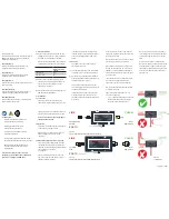
Voltage
measurement inputs
10 - 500 Vac
40 - 100 Hz
Current transformer
Power supply
230 Vac
50/60 Hz
X/5
1A
1A
1A
X/5
1A
1A
58mm
32mm
48mm
90
m
m
36
m
m
45
m
m
6
2
m
m
53mm
Re
t
t
t-2
(o-F)
(u-F)
r-t
t-2
r-t
55 Hz
45 Hz
Under Frequency
Over Frequency
L1,L2,L3
Normal
Normal
f(Hz)
Over and/or Under Frequency Protection : ( 40 – 70 Hz )
Under Frequency be able to set between
(u-F)
= 40 Hz ...[(o-F) -0,4]
Over Frequency be able to set between
(o-F)
=[(u-F) + 0,4]...70 Hz
If required , it can be set only under frequency or only over frequency
protection as well as both of protection can be disabled.
If o-F = 55 Hz and u-F = oFF set, device works as over
frequency protector only. (if system frequency above 55 Hz, under
screen displays
o-F
warning and end of time t-2 relay switch off its
output contact )
if o-F = oFF and u-F = 45 Hz set , device works as under
frequency protector only . (if system frequency below 45 Hz, under
screen displays
u-F
warning and end of time
t-2
relay switch off its
out contact.)
if o-F = oFF and u-F = oFF set, frequency protection is disabled.
LOCKING FUNCTION :
It can be controlled by two parameters. Locking time and
Locking counter. If the number of opening reaches the adjusted
locking counter withing the adjusted locking time then device
switch off its contact and locks its functions until the user
pressed
Reset
button.
If the locking counter is adjusted to
oto
then this function is
disable and device never locks itself.
L-t : Locking Time
( 001 – 060 min. )
It is well know the frequently occurring faults may damage
system. For that the device when number of faults reaches the
adjusted locking number within this locking time. This way the
system is protected and user has chance to investigate the
problem.
L-C : Locking Counter
( oto , 001 – 010 piece )
The number of faults allowed within the period L-t. If number of
faults exceeds this adjusted counter value device locks itself.
In this case (
- - -
) warn
appears on
its screen. User must press
Reset button then the fault passes in order to unlock the device.
If
L- C
is set to
oto
then this property is disabled.
V
Re
t
t
(o-U)
(u-U)
r-t
Over Voltage
1. Error
VL
Normal
Normal
L- C (number of lock) = 2 piece
L- t (lock time)
= 3 min.
if select ;
t-1
t-1
r-t
Pushed to Reset button
and Lock have reseted.
Locked occurred
< 3 minutes
Over Voltage
2. Error
ATTENTION !!!
- Clean the device using dry dust cloth after turned off device.
- Read and follow the instruction on this manual and attached label.
Connection :
TECHNICAL INFORMATION:
Rated Voltage (Un)
: 230Vac (L-N)
Operating Range
: (0,8-1,1) x Un
Frequency
: 50 / 60 Hz
Supply Power Consumption : < 4VA
Current Transformer Ratio
: X / 5A
Current Measurement Range : (for seconder current)
0,05 - 6 Amp AC
Voltage Measurement Range : 10 - 500 Vac, 40 - 100Hz
(X1, X2)
Voltage Measurement
Power Consumption : <1VA (for one phase)
Measurement Sensitivity
: %1±1 digit
Contact Current
: Max. 3A / 240Vac
Device Protection Class
: IP 20
Connector Protection Class : IP 00
Temperature
: - 5 °C .... + 50 °C
Connection Type
: To connection rail in electrical panel
Dimension
:
Power supply
230 Vac
50/60 Hz
Current transformer


