background image

Installation Manual

Installation

29

k2evo702 - 201610

Kaba c-lever and variants

4.4.2

c-lever short plate variant

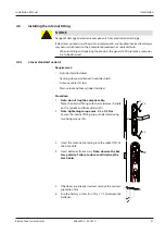
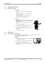
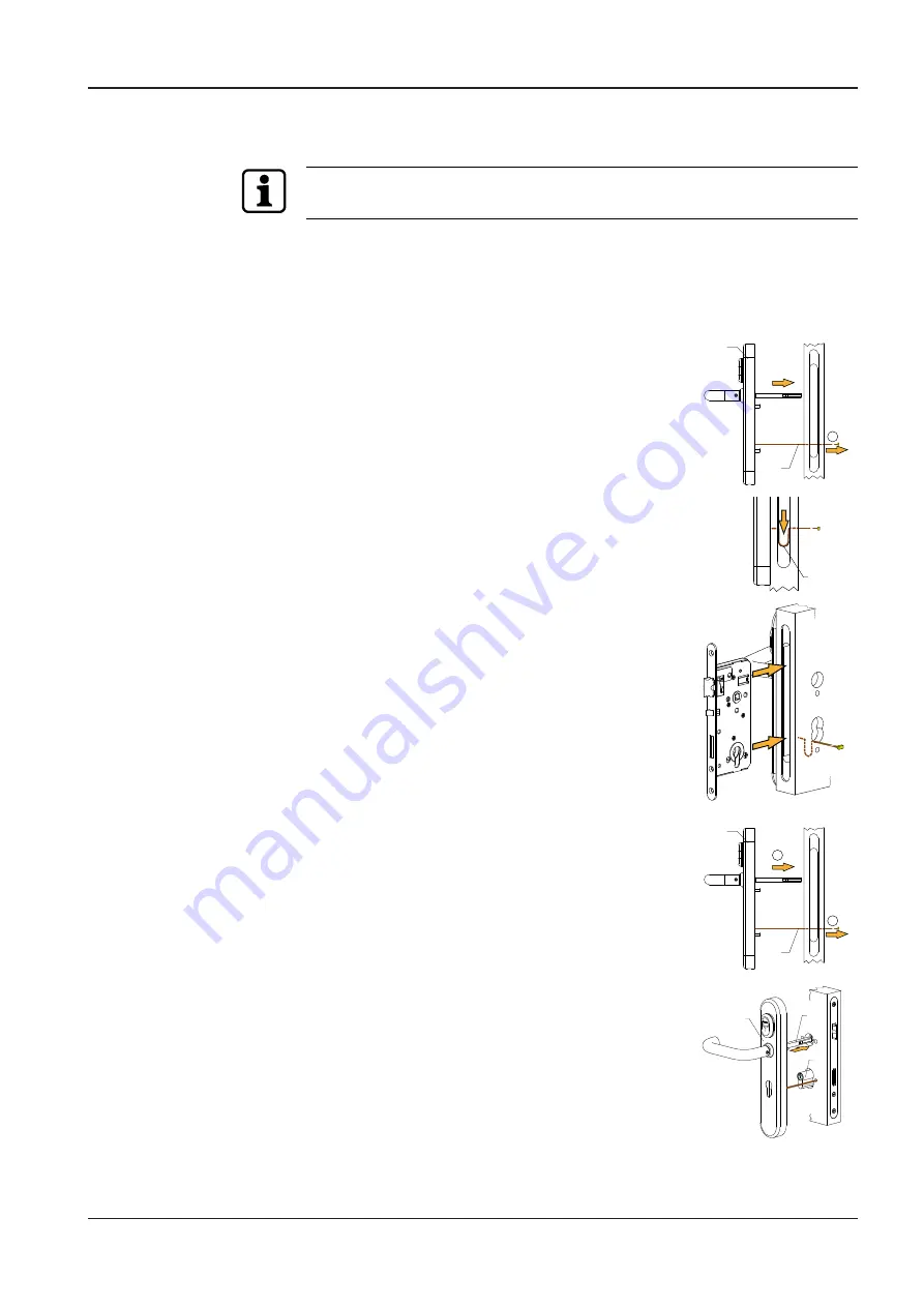
Once the outside shield is installed, the pressure on the coupling of the coupling unit
must be relieved. To do this, pull the spindle inwards.

Requirement:

Mortise lock is 

not

 installed yet

Procedure:

1.

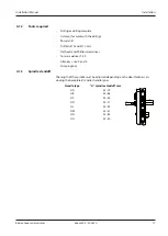
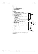
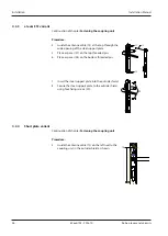
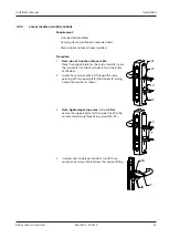
Guide the antenna cable (13) through the cylinder
cut-out of the door as shown (A).

8

13

A

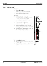
2.

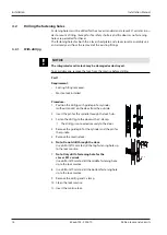
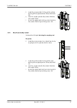
Lay the antenna cable (13) in the lock mortise as
shown.

13

3.

Note: do not shift and/or trap the antenna cable.

Push the mortise lock into the mortise.

4.

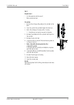
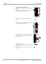
Guide the outside shield (8) with tightened spindle
into the lock hub (B).
Retighten the antenna cable (13) in the process (A).

8

13

B

A

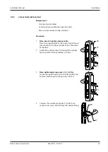
5.

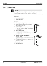
Place the outside shield (8) on the outside of the door.

8

27

50

6.

Secure the mortise lock to the door.

7.

Push the lock cylinder (50) into the mortise lock.

8.

Secure the lock cylinder with the cylinder fixing screw
(but do not tighten yet).

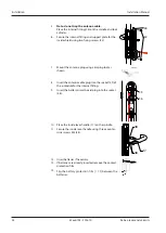
9.

Pull the spindle (27) inwards.

Result:

The mortise lock, lock cylinder and outside shield are installed on the door.

Содержание c-lever 2662-K5

Страница 1: ...Kaba c lever and variants Installation Manual EN k2evo702 201610 ...

Страница 2: ...and Phone 41 44 931 61 11 www kaba com Kaba GmbH Access Workforce Management Albertistraße 3 78056 Villingen Schwenningen Germany Phone 49 7720 603 0 www kaba com This document must not be reproduced in any way or otherwise further used without the written consent of Kaba AG All product names are trademarks of the respective companies Copyright 2016 Kaba AG All rights reserved k2evo702 201610 ...

Страница 3: ...rt plate 12 3 2 3 Additional fixtures for c lever rosette assembly 12 3 2 4 Additional fixtures for c lever wireless 12 3 2 5 Accessories 12 3 3 Technical data 13 3 3 1 Dimensions 14 3 3 2 Versions 15 3 4 Conformity 15 4 Installation 16 4 1 Requirements 16 4 1 1 Door components 16 4 1 2 Tools required 17 4 1 3 Spindle standoff 17 4 2 Drilling the fastening holes 18 4 2 1 With drill jig 18 4 2 2 Wi...

Страница 4: ... 1 For all c lever variants 39 4 7 Other variants 39 4 7 1 Installing variant with wide plate 39 4 7 2 Installing variant for special lever handle styles 40 5 Operation 41 5 1 Operating the c lever 41 5 2 Opening with user media 41 6 Maintenance 42 6 1 Maintenance table 42 6 2 Cleaning 42 7 Service 43 7 1 Replacing batteries 43 7 2 Replacing the antenna 44 7 3 Replacing the e module 44 7 4 Reset I...

Страница 5: ...nd all optional features and functions Options are subject to a charge and therefore only available if purchased Different options and equipment features are not available in every variant or in all countries 1 2 Target group This document is intended for specialist personnel only The descriptions are intended for specialist staff trained by the manufacturer The de scriptions are no replacement fo...

Страница 6: ...ion Product designation c lever Kaba c lever Programmer 1460 Kaba programmer 1460 Programmer 1364 Kaba programmer 1364 Component c lever fitting Symbols Symbols Acoustic signal Visual signal 1 6 Hazard categories Instructions with information on what to do and not to do to prevent injury and ma terial damage are denoted specially Please follow all hazard instructions These are intended to help pre...

Страница 7: ...Tips on using the product are useful pieces of information They help to make best use of the product and its functions 1 8 Symbols Symbols with the following meanings are used for hazards depending on hazard source General hazard Hazard from electric shock Risk of explosion Risk to electronic components from electrostatic discharge ...

Страница 8: ...ge to electronic components from electrostatic discharge If electronic printed circuit boards and components are handled incorrectly damage may occur which leads to their complete breakdown or sporadic faults When installing and repairing the product the general ESD protective measures are to be observed When handling electronic components wear the ESD wrist strap Connect the end of the strap to a...

Страница 9: ...xplode or burst explosively Improper handling of lithium batteries can lead to fires and explosions Only replace lithium batteries with batteries of the same type Do not open drill through or squash lithium batteries Do not burn lithium batteries or expose them to high temperatures Do not short circuit lithium batteries Do not recharge lithium batteries ...

Страница 10: ...oded diagram of structure of variant 2621 1 Antenna housing 16 Lever handle bearing 31 Fixing screw 2 Antenna 17 Inside lever handle 32 Threaded pin 3 Antenna circuit board 18 Fixing screw for lever handle 4 Frame housing 19 Inside shield 5 Fixing screw for lever handle 20 Battery protection film 6 Lever handle 21 Connection cable 7 Lever handle bearing 22 Battery circuit board 8 Outside shield 23...

Страница 11: ...xing screws 1 steel support plate for outside shield 1 centring sleeve 2 spacer sleeves 2 pull protection washers Additional fixing screws Screw pack Top bottom fixing screws Middle fixing screws Long arbour mm Dimension mm Door thick ness mm Dimension mm Door thick ness mm No 1 105 M5 x 50 38 44 M5 x 40 38 40 M5 x 45 41 45 M5 x 60 45 54 M5 x 50 46 50 M5 x 55 51 55 M5 x 70 55 58 M5 x 60 56 58 No 2...

Страница 12: ... Additional fixtures for c lever rosette assembly 1 support plate for outside shield 1 support plate for inside shield 3 fixing screws M5 x 50 mm for internal fitting and outside shield 2 fixing screws M5 x 12 mm for outside shield support plate 2 fixing screws M5 x 6 mm for inside shield support plate 3 2 4 Additional fixtures for c lever wireless Wireless module with connection ter minal 64 Plug...

Страница 13: ...5 C 70 C The temperature range depends on the battery manufacturer s specifica tions Humidity 0 95 rel hum non condensing Climate Not suitable for heavily corrosive atmospheres chlorine ammonia Rooms Not to be used in poten tially explosive environ ments Standards Fire safety DIN 18273 tested in ac cordance with EN 1634 1 DO 20 31 EN 179 According to test certific ate 0432 BPR 0061 Kaba 0432 BPR 0...

Страница 14: ...ption Installation Manual 14 k2evo702 201610 Kaba c lever and variants 3 3 1 Dimensions Fig 2 Dimension drawing narrow version Europrofile cylinder PZ 53 6 Fig 3 Dimension drawing wide version Europrofile cylinder PZ ...

Страница 15: ...for Europrofile PZ or round profile RZ cylinder versions Hole centre 0 1 Versions 55 PZ 57 70 72 74 RZ 78 78 PZ 85 88 90 92 94 RZ 98 PZ 100 5 RZ 3 4 Conformity This product conforms to the EU directives 2014 35 EU Low Voltage Directive 2014 53 EU Radio Equipment Directive 2014 30 EU EMC Directive 2011 65 EU RoHS Directive ...

Страница 16: ...a lock cylinder to be ensured it is necessary to install door locks with key operated latch Lock cylinder The fitting is independent of the lock and lock cylinder and can be used for cylinder holes with 17 mm Europrofile or 22 mm round profile The fitting can also be used on the door without a cylinder hole for half cylinders Cylinder standoff NOTICE The cylinder standoffs must be checked before t...

Страница 17: ...ll Drill bits Ø 9 and Ø 13 mm Flat head and Phillips screwdriver Torx screwdriver T 20 Allen keys size 2 and 3 Crimping tool 4 1 3 Spindle standoff The length of the spindle must be adjusted depending on the door thickness in cluding the backplate s and or handle types Handle type A spindle standoff mm HA 42 79 A HB 42 68 HC 42 56 HD 42 77 HL 42 92 HM 42 51 HN 42 85 HO 42 50 ...

Страница 18: ...isting fitting removed Mortise lock installed Procedure 1 Position the drill jig with guide pin for cylinder without mount on the door from the outside 2 Insert the pin for the spindle through the lock hub 3 Fasten the drill jig to the door with a C clamp ð The drill jig is connected securely to the door 4 Remove the guide pin for the cylinder and the pin for the spindle 5 Remove the mortise lock ...

Страница 19: ...door 4 Remove the guide pin for the cylinder and the pin for the spindle 5 Remove the mortise lock 6 Use drill bit Ø13 mm to drill the top fastening hole up to the lock mortise 7 Note Only drill a fastening hole for the c lever ES1 variant Use drill bit Ø9 mm to drill the middle fastening hole up to the lock mortise 8 Use drill bit Ø9 mm to drill the bottom fastening hole up to the lock mortise 9 ...

Страница 20: ...drilling template over the spindle and align it parallel to the forend 3 Mark the drill holes ð Drill holes for the fastening holes are marked on the door leaf 4 Remove the mortise lock 5 Note Do not drill through the door Use drill bit Ø13 mm to drill the top fastening hole up to the lock mortise 6 Note Only drill a fastening hole for the c lever ES1 variant Use drill bit Ø9 mm to drill the middl...

Страница 21: ...ill holes for the fastening holes are marked on the door leaf 4 Remove the mortise lock 5 Use drill bit Ø13 mm to drill the top fastening hole up to the lock mortise 6 Note Only drill a fastening hole for the c lever ES1 variant Use drill bit Ø9 mm to drill the middle fastening hole up to the lock mortise 7 Use drill bit Ø9 mm to drill the bottom fastening hole up to the lock mortise 8 Clean the l...

Страница 22: ...ocated on one side of the front of the coupling unit housing The direction pin is in serted into the coupling unit in such a way that when an outside lever handle is turned right or left the R or L respectively matches the marking on the coupling module Requirement Lever handle exists for spindle 9 mm of coupling unit Procedure 1 Align the direction pin 10 see information above 2 Place the lever h...

Страница 23: ...up towards the threaded pin Inserting the spindle Procedure 1 Select the spindle based on the diameter of the lock hub 2 If a 7 mm spindle is used place the reduction sleeve 33 on the spindle 27 Note when using the reduction sleeve ensure that the release of the sleeve is facing upwards 29 27 32 33 3 Insert the spindle in the square of the coupling unit 29 with the groove facing the cylinder fixin...

Страница 24: ...of the outside handle and insert the coupling unit into the outside shield 29 3 Note Place the coupling unit evenly and securely in the outside shield Use a screwdriver to push the top cushion under the lug A and push the top part of the coupling unit into the outside shield B B A 4 Use a screwdriver to push the bottom cushion under the lug C and push the bottom part of the coupling unit into the ...

Страница 25: ...edure 1 Secure the coupling unit using the lever handle fix ing screw 5 5 2 Connect the plug of the coupling unit to the white socket 46 49 46 3 Connect the plug of the antenna cable to the black socket 49 Result The coupling unit is securely fastened in the outside shield The antenna circuit board is connected ...

Страница 26: ...support plate 37 13 38 5 Place a spacer 37 on the top threaded pin 6 Place a spacer 38 on the bottom threaded pin 7 Insert the steel support plate into the outside shield 39 8 Secure the steel support plate to the outside shield using four fixing screws 39 4 3 4 Short plate variant Continuation of chapter Fastening the coupling unit Procedure 4 Guide the antenna cable 13 on the left next to the co...

Страница 27: ...he outside shield using two fixing screws 42 4 3 5 Rosette assembly variant Continuation of chapter Fastening the coupling unit Procedure 4 Guide the antenna cable 13 on the left next to the coupling unit in the outside shield as shown 13 5 Guide the antenna cable 13 through the wide opening of the support plate for the outside shield 41 41 13 43 6 Insert the support plate for the outside shield i...

Страница 28: ...coupling unit must be relieved To do this pull the spindle inwards An additional drill hole is required in the door for the c lever ES1 variant Requirement Existing fitting removed Mortise lock installed Procedure 1 Push the lock cylinder 50 into the mortise lock 2 Secure the lock cylinder with the cylinder fixing screw but do not tighten yet 3 Guide the antenna cable 13 through the top fasten ing...

Страница 29: ...tenna cable 13 in the lock mortise as shown 13 3 Note do not shift and or trap the antenna cable Push the mortise lock into the mortise 4 Guide the outside shield 8 with tightened spindle into the lock hub B Retighten the antenna cable 13 in the process A 8 13 B A 5 Place the outside shield 8 on the outside of the door 8 27 50 6 Secure the mortise lock to the door 7 Push the lock cylinder 50 into ...

Страница 30: ...ting fitting removed Mortise lock installed Procedure 1 Push the lock cylinder 50 into the mortise lock 2 Secure the lock cylinder with the cylinder fixing screw but do not tighten yet 3 Guide the antenna cable 13 through the bottom fastening hole of the removed rosette 4 Guide the outside shield 8 with tightened spindle 27 into the lock hub 5 Place the outside shield on the outside of the door 6 ...

Страница 31: ... installed Centring sleeve positioned in outside shield Antenna cable 13 laid Mortise lock and lock cylinder installed Procedure 1 Note do not trap the antenna cable Place the internal fitting with the inside lever handle on the spindle and lock cylinder 50 24 13 24 50 2 Note tightening torque max 2 5 0 5 Nm Secure the internal fitting and outside shield using two fixing screws 24 3 4 Insert the a...

Страница 32: ...35 24 26 36 24 2 Screw in the top fixing screw 24 with a pull protec tion washer 35 3 Screw in the middle fixing screw 24 4 Screw in the bottom fixing screw 24 with a pull pro tection washer 36 5 Note tightening torque max 2 5 0 5 Nm Secure the internal fitting and outside shield using three fixing screws 24 6 Insert the antenna cable plug into the socket 59 of the e module for the internal fittin...

Страница 33: ...a cable Place the support plate for the inside shield 40 over the spindle 27 and lock cylinder 50 on the inside of the door 27 40 50 13 2 Guide the antenna cable 13 through the cylinder opening under the lock cylinder as shown 3 Note tightening torque max 2 5 0 5 Nm Secure the support plate for the inside shield to the outside shield using two fixing screws M5 24 24 4 Unscrew the inside lever hand...

Страница 34: ...ntenna plug using crimping tool as shown 8 Insert the antenna cable plug into the socket 59 of the e module for the internal fitting 59 56 9 Insert the battery circuit board plug into the socket 56 10 Place the inside lever handle 17 on the spindle 17 48 48 11 Secure the inside lever handle using three counter sunk screws M4 48 12 Insert batteries if necessary 13 If batteries are already inserted ...

Страница 35: ...e support plate for the inside shield 41 over the spindle 27 and lock cylinder 50 on the inside of the door 27 41 50 13 2 Guide the antenna cable 13 through the wide opening of the support plate the bottom fastening hole of the rosette as shown 3 Note tightening torque max 2 5 0 5 Nm Secure the support plate for the inside shield to the outside shield using three fixing screws M5 24 24 4 Unscrew t...

Страница 36: ... fixing screws 42 7 Mount the antenna plug using crimping tool as shown 8 Insert the antenna cable plug into the socket 59 of the e module for the internal fitting 59 9 Place the inside lever handle 17 on the spindle 17 48 48 10 Secure the inside lever handle using three counter sunk screws M4 48 11 Insert batteries if necessary 12 If batteries are already inserted remove the contact protection fi...

Страница 37: ...ant version See list below c lever standard variant 4 5 1 c lever ES1 variant 4 5 2 c lever short plate variant 4 5 3 c lever rosette assembly variant 4 5 4 2 For doors that have a mortise lock with a micro switch Connect mortise lock to micro switch and wireless module a Remove wireless module 52 from the internal fit ting b Remove connection terminal 53 from the pin header of the wireless module...

Страница 38: ... cables on the pin header of the wireless module e Insert wireless module into the internal fitting Further information on the use of potential locks and door contacts can be found in the Wireless planning guideline This documentation and further product document ation can be downloaded from Kaba s website following registration ...

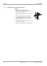
Страница 39: ... the internal fit ting Audibly clicks into place 2 Secure the inside shield with a fixing screw M3 25 3 Tighten the lever handle fixing screw 18 4 Align the lock cylinder and secure using the cylinder fixing screw 5 Carry out a function check 19 25 18 4 7 Other variants 4 7 1 Installing variant with wide plate In order to ensure improved plate support for the inside shield of variants with a wide ...

Страница 40: ...e shield 19 and lever handle on the spindle 2 Align the internal fitting and push on to the lock cylin der 3 Turn the inside shield 90 to the internal fitting 4 Note tightening torque max 2 5 0 5 Nm Secure the internal fitting and outside shield using two fixing screws 24 5 Place the inside shield parallel on the internal fitting Audibly clicks into place 6 Secure the inside shield with a fixing s...

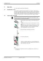
Страница 41: ...first time access authorisations for the relevant system software must be transmitted to the Components 2 1 2 Beep 1 Hold the authorised user medium in front of the antenna of the fitting The acoustic and visual signals1 indicate the access author isation Note The c lever s opening time is limited after this time has elapsed the c lever closes automatically Upon delivery the opening time is approx...

Страница 42: ... All components Function check in accordance with in structions 12 months Replacing the batteries 24 months1 Clock compon ents Check and set clock time with the system software 12 months Firmware update For functional modifications as required Table 3 Maintenance interval evolo components Key 1 c lever with lithium batteries 6 2 Cleaning Only disinfection agents that are explicitly formulated for ...

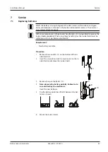
Страница 43: ... the inside shield completely When using these handle styles the inside shield must be withdrawn as far as possible and rotated 90 Requirement New battery available Procedure 1 Remove the screw M3 13 on the bottom of the in side shield 2 2 13 2 Insert the screwdriver into the countersink on the in side shield and remove the inside shield 3 Remove the spent batteries 10 10 8 9 4 5 Note observe the ...

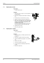
Страница 44: ...s are an exact fit in the upper sleeves The lower sleeves remain free Place the rectangular intermediate circuit board on the antenna on the inside of the outside shield 6 Tighten both screws M4 7 Mount the outside shield 1 2 12 8 57 7 3 Replacing the e module Requirement Inside shield removed Procedure 1 Remove the antenna and battery cables from the e module 15 2 Remove the screw M3 58 from the ...

Страница 45: ...NI reset short circuit these contacts with electrically conductive tweezers Before short circuiting present a valid master medium or user medium 1 Disassemble Inner shield 2 Localise both contacts on the e module See Chapter Replace e module 3 Using the tweezers short circuit the INI reset contacts for approx 3 s ð Successful INI reset is confirmed using an acoustic signal 7 5 Emergency power supp...

Страница 46: ...y battery opening device Programming cable product no 1355 42 Adapter programming pin product no 1355 42A New batteries 2x 1 5 V AA lithium Procedure 1 Connect the emergency battery opening device to the programming cable and programming pin 2 Insert the programming pin into the programming socket of the antenna 3 Hold the authorised user medium in front of the antenna 4 Hold down the button on th...

Страница 47: ...confirmed via acoustic and visual signals 8 x short 8 x short red Self test could not be com pleted Check or replace the coupling unit Door does not open authorisa tion by an authorised user me dium is confirmed via acoustic and visual signals 4 x short 4 x short red Medium not programmed Outside the time window Program medium Check time profiles Door does not open authorisa tion by an authorised ...

Страница 48: ...coupling unit Deactivate TimePro function Replace coupling unit The use of a master or user me dium is not confirmed by the component Antenna connection error or faulty electronics Check connection between antenna and electronics Door is always open door does not open or close at pro grammed time Time is missing on e module or is not correctly set Incorrect programming Set time check programming R...

Отзывы: