


Version 02/15/2016
Page 26 of 40
Mounting instructions 82132/3xxx CB 30
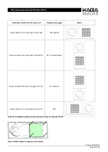
10.4
Interfaces of the input unit
Connection Type
Description
Specification
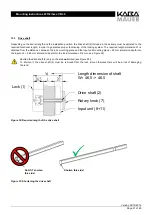
Cable with
plug
Communication line
to lock
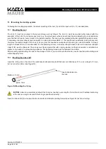
Connecting cable and plug to lock
6-pin connector
I/O mini
USB
connector
Data interface to PC
Connects the input unit to the PC by means of the
Kaba Mauer CB30 PC cable, in order to read the
audit or configure the lock
As pre-assigned internally.
Notice: Special
interface, use only
original Kaba Mauer
CB30 PC cable!
Table 8: Overview input unit connections
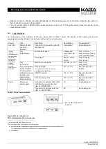
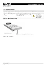
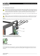
Figure 26: Input unit connection
I/O mini USB connector
Connecting cable to the lock with plug