background image

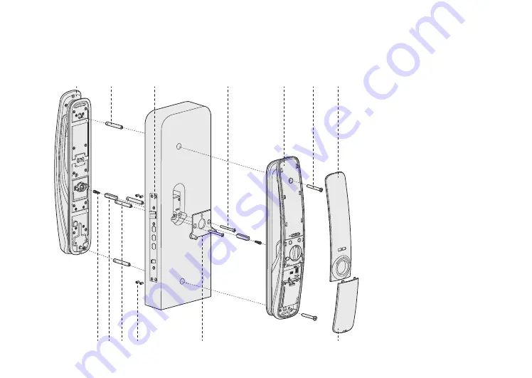
Explosive view

Understanding the installation of a three-dimensional assembly drawing is beneficial to understand lock 

structure.

1

13

2

3

4

5

6

7

8 9 10 11

1.Front panel

2.M6  Connecting screw bolt

3. Mortise

4.M5 screws (4)

5.Back panel

6.Upper M6 Screw 

7.Back cover

8.Springs (2)

9. Square shaft (2)

10. M5 connecting screw bolt (4)

11. Screws for mounting mortise (4)

12.Mounting Plate

13.Below M6 screw

14. Battery cover

12

Содержание Lamborghini Legends

Страница 1: ...Kaadas Lamborghini Legends User Manual ...

Страница 2: ...read the installation instruction carefully before you install this lock and then install the product according to the instruction Our company will not assume any responsibility for direct or indirect product problems other hazards and losses if you don t follow the instruction to install ...

Страница 3: ...ser fingerprint Add user card Delete user PIN code Delete user fingerprint Delete user card optional Set the door opening mode System system Record query Extend function optional 5 Use your smart lock Unlock from outdoor Unlock by mechanical key Unlock from indoor Auto mode Manual mode Unlock by touching inside built in sensor handle Emergency Knob Defence mode Volume Adjustment Contents 6 Other fun...

Страница 4: ...install it by yourself After the door lock is installed please modify the default master PIN code immediately and keep the mechanical key in a safe place Don t disclosure PIN code to the unknown person When low battery alarm is triggered please replace all the batteries in time Warning Do not place battery closing to fire in case of explosion Do not short circuit the two poles of the battery lead w...

Страница 5: ...contents are subject to the actual packaging contents Front panel with rubber gasket Monuting plate User card Screw pack User manual warranty card Micro fibor Wiper User manual Screw pack Back panel with rubber gasket Installation template Mortise Strike plate Mechanical key warranty card ...

Страница 6: ...derstand lock structure 1 13 2 3 4 5 6 7 8 9 10 11 1 Front panel 2 M6 Connecting screw bolt 3 Mortise 4 M5 screws 4 5 Back panel 6 Upper M6 Screw 7 Back cover 8 Springs 2 9 Square shaft 2 10 M5 connecting screw bolt 4 11 Screws for mounting mortise 4 12 Mounting Plate 13 Below M6 screw 14 Battery cover 12 ...

Страница 7: ...Loosen the screw counterclockwise with an Allen wrench then take out face plate 2 Take out latchbolt and rotate 180 then take back latchbolt Face plate 3 Install back faceplate and tighten screws then work done Right out open Right in open Left out open Left in open Allen wrench Face plate Allen wrench ...

Страница 8: ...panel Finally mounting the front panel by mounting plate Drill bores following the installation template and then put the mortise into the door and tighten the four mounting screws Mortise Connecting Cable M6 Connecting Screw bolt M6 Connecting Screw bolt M5 screw bolts Square Shaft Spring Mortise Connecting cable Front Panel connector Front Panel Connector Note According to the thickness of the d...

Страница 9: ...l connector and mortise connector into the corresponding interfaces on the back panel The excess cable plugs back the cable holes and then tighten the screws to fix the back panel Take out back panel and battery cover Square Shaft Spring Interface for front panel connector Interface for mortise connector ...

Страница 10: ...Install the back cover and batteries 4 pcs or 8 pcs then install battery cover Check whether each part is installed well ...

Страница 11: ...Battery cover Doorbell Fingerprint sensor Open close indicator Privacy mode indicator Keypad Card Reader area Low voltage indicator Mechanical key hole Micro USB interface Emergency power Reboot button Front panel Back panel Unlock inside sensor 3 Overview ...

Страница 12: ...should enter user number When you need to delete single user you can delete single user pin code according to user numer You can fill in the user information in this table for easy management Security mode Common mode Master pin code the master code before entering master mode the master code before entering master mode User Pin code User fingerprint Method of entering master mode User card Note Bef...

Страница 13: ...for user setting then press 1 again to add user fingerprint put your fingerprint on the sensor until voice prompt setting succeeded Press1 for user setting then press 1 to add user card Put card on the reader until voice prompt setting succeeded Press 1 for user setting then press 2 to add one time pin code enter new one time Pin code with confirmation Enter new one time Pin code with confirmation aga...

Страница 14: ...r setting press 5 to delete users then press 4 to delete all user cards Voice prompt deletion succeeded Enable Disable Dual validation Under master mode Press 1 for user setting then press 6 to enable or disable dual verification Voice prompt setting succeeded Enable Disable auto mode Under master mode Press 1 for user setting then press 7 enable or disable auto mode Voice prompt setting succeeded ...

Страница 15: ...nrolled finger properly on the fingerprint sensor area After voice prompt door opened push or pull handle to open the door Place the enrolled card properly on the card icon area After voice prompt door opened pressing down the handle to open the door Fingerprint sensor Card Reader area Note 1 Under common mode when you verify fingerprint card or Pin code more than 5 times incorrectly the lock will ha...

Страница 16: ...sensor handle disabled please press open button to unlock or enable sensor again Unlock by mechanical key Auto manual mode You can unlock by mechanical key if you forget pin code the battery run out or system error occurs Insert the mechanical key and then rotate 180 to unlock 1 Take out the battery cover there is a A M switch 2 A represents Auto mode in which it will automatically lock after clos...

Страница 17: ...ou pressed the doorbell button the Doorbell sounds when system is in voice mode you can long press 0 button after keypad lighten to turn off voice temporarily it will recover once keypad waked up again when system is in mute mode you can long press 0 button after keypad lighten to turn on voice temporarily It will recover once keypad waked up again ...

Страница 18: ...n the lock from outside you can use 5V power bank to charge the door lock via Micro USB port After the door is unlocked please replace all batteries immediately When battery voltage is lower than 4 8V voice prompts Low battery please replace all batteries at each unlocking Please replace all batteries immediately and do not mix old batteries and new batteries together in replacement Press the rebo...

Страница 19: ...t low battery please change battery in time please follow the prompt to change battery in time Extended network module is reserved for smart home system please contact kaadas for more details Battery cover Battery cover Interface for extended module Extended module ...

Страница 20: ...www kaadasgroup com Shenzhen Kaadas Intelligent Technology co Ltd reserves all rights for the final interpretation for this user manual And the mannual is subject to be changed without notice ...

Отзывы: