K2L MOCCA compact 2.3 Скачать руководство пользователя страница 12

MOCCA compact 2.3 

Pin out of the Connectors        12 

3.1.3 

Low Speed CAN / LIN 

One fault tolerant, one single wire CAN interfaces and two LIN channels are combined on this DE-9 
socket. 

The provided GND pin must not be used unless there is no other GND connection. This pin must not 
be used for supply purpose.  


PIN no. 

Signal 

Description 

LIN1 

1

st

 LIN Channel 

CAN2-Low 

LOW-level CAN bus line 

GND 

Signal ground 

Do not connect 

Do not connect 

Do not connect 

CAN2-High 

HIGH-level CAN bus line 

LIN2 

2

nd

 LIN Channel 

CAN6-High 

HIGH-level CAN bus line (single wire) 

Table 3-4: Pinning of Connector Low Speed CAN 2/6 


3.1.4 

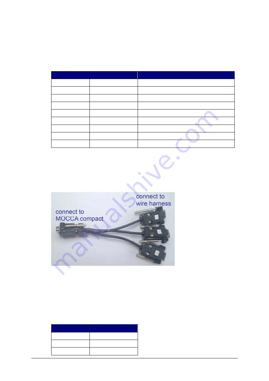
CAN Breakout Cable (optional Accessory)  

Most wire harnesses connect only one CAN bus to each DE-9 connector. Usually they connect CAN-
Low line to pin 2 and CAN-High line to pin 7. Pin 3 is usually GND. 


Illustration 3-2: CAN Breakout Cable - each of the Sockets 

I

II

 and 

III

 connect to 

one pair CAN-L/CAN-H from the MOCCA compact 

The CAN breakout cable can be used to adapt from the compact pinning used on the MOCCA 
compact 2.3 (where up to 3 CAN are available on one DB-9) to three DB-9 sockets compliant to the 
standard pinning. The CAN bus with the lowest index on this connector on the MOCCA compact 2.3 
is routed to the DB-9 socket with the marking “

I

” and the CAN bus with the next higher index on this 

connector is routed to the adapters’ DB-9 socket with the marking “

II

” and so on.  

If the adapter is used on the connector “High Speed CAN 1/3/5” for example the connection is as 
follows: 

CAN no. 


Socket 

1 (High Speed) 

3 (High Speed) 

II 

5 (High Speed) 

III 

Содержание MOCCA compact 2.3

Страница 1: ...MOCCA compact 2 3 Document Release MOCCA compact 2 3...

Страница 2: ...means electronic or mechanical including photocopying and recording for any purpose other than the purchaser s personal use without prior written permission from K2L GmbH K2L and the K2L logo are regi...

Страница 3: ...afety instructions III Document History Version Brief description of change V1 0 000 Initial Release V01 01 00 CAN Breakout cable added Image of back panel power CAN added types of LIN and single wire...

Страница 4: ...hnical Specification 9 3 Pin out of the Connectors 10 3 1 Connectors on the Back 10 3 1 1 High Speed CAN 10 3 1 2 FlexRay 11 3 1 3 Low Speed CAN LIN 12 3 1 4 CAN Breakout Cable optional Accessory 12 3...

Страница 5: ...View on the Front 14 Tables Table 1 1 Abbreviations 7 Table 1 2 Technical Specification 9 Table 2 1 Pinning of Connector High Speed CAN 1 3 5 10 Table 2 2 Pinning of Connector High Speed CAN 2 4 6 11...

Страница 6: ...st device in the chain is able to take Do not cascade more than 8 devices in chain For all setups a fuse of max 4A in the supply cable to the first device or the use of the current limitation of your...

Страница 7: ...e Bus Minus in FlexRay BP Line Bus Plus in FlexRay CAN Controller Area Network automotive bus system CPU Central Processing Unit EHC External Host Controller FOT Fiber Optical Transceiver FR A B FlexR...

Страница 8: ...ions may not be available in a specific configuration 6 CAN busses two of them with selectable transceiver high or low speed and high speed or single wire MOST25 MOST50 or MOST150 1 FlexRay with chann...

Страница 9: ...mption standby 25 mA Relay for external Load Potential free shutter max 5A 12V DC Low Speed CAN Transceiver NXP TJA 1054 High Speed CAN Transceiver NXP TJA 1041 Single Wire CAN Transceiver OnSemi NCV7...

Страница 10: ...escribes the respective connectors pinning Illustration 3 1 Connectors seen from the supply side 3 1 1 High Speed CAN The provided GND pins must not be used unless there is no other GND connection The...

Страница 11: ...CAN4 High HIGH level CAN bus line Table 3 2 Pinning of Connector High Speed CAN 2 4 6 3 1 2 FlexRay The provided GND pin must not be used unless there is no other GND connection This pin must not be...

Страница 12: ...nect only one CAN bus to each DE 9 connector Usually they connect CAN Low line to pin 2 and CAN High line to pin 7 Pin 3 is usually GND Illustration 3 2 CAN Breakout Cable each of the Sockets I II and...

Страница 13: ...owered by the optional available wall power supply or by any other power supply which is capable to deliver 12V and 1A If the wall power supply is not used the included power cable has to be used to c...

Страница 14: ...1 USB The USB port is a standard USB B type receptacle 3 2 2 Relay The relay is able to switch 5A as a potential free shutter The two left pins and the two rights are internally connected Please see...

Страница 15: ...The LAN connector is a RJ45 receptacle according to TIA 568 3 2 5 LEDs The MOCCA compact 2 3 offers seven LED positions where UD1 UD4 and Operation are dual color positions LED Position Red Green Acti...

Страница 16: ...e bus Termination resistors can be ordered separately from K2L 4 1 2 Fault Tolerant Transceiver As fault tolerant CAN transceiver a TJA1054 from NXP is used Fault tolerant CAN busses usually have a di...

Отзывы: