Advanced Operations
In order to use USB function the host which DSO112A is to communicate with is required
to install driver supporting the USB-Uart bridge CP2102. Please use the following link
to download driver and install it (refer to documents accompanying).
www.silabs.com/products/mcu/pages/usbtouartbridgevcpdrivers.aspx
USB Connection
Serial Port Parameters
For the main firmware serial port parameters are fixed to 115200 bps and 8-N-1.
For the bootloader serial port parameters are fixed to 9600 bps and 8-N-1.
Waveform Data Upload
Please refer DSO112A User Manual for detailed instructions.
The DSO112A User Manual is available at
Δ
Δ
T cursors and
V cursors
Δ
T and
cursors can be turn on or off by touching or button at the menu screen.
Δ
V
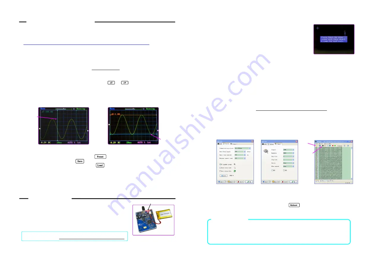
To change cursor position touch the cursor you want to change to highlight it. Then touch
anywhere of the panel and scroll horizontally (for
. You will see the
highlighted cursor moves and readouts change accordingly (see Fig. 6 and Fig.78).
Δ
Δ
T) or vertically (for V)
Maintenance
Charging the Battery
DSO112A contains a built-in smart Li-ion battery charger. Simply
connect the unit to USB power supply charging will start
automatically. A red LED will light up (which can be seen from
outside) indicating charge is undergoing. The charger will stop
automatically once the battery is fully charged. (Fig. 8)
Touch Panel Calibration
The touch panel has been calibrated before shipping. In case of the
touch panel doesn
’
t work properly it can be re-calibrated. Please
follow the steps below to perform touch panel calibration.
1 ) Power up the scope. At the main booting screen push [P]
button to enter Setup mode.
2 ) Press and hold [P] button in Setup mode to enter touch
panel calibration state, as shown in Fig. 9.
3 ) Use a pointed object to touch the center of each cross 8 times,
as accurately as you can. You will see three crosses, one after another. Do not touch more
than 8 times for each cross.
4 ) After you finish the third cross touch anywhere of the panel to verify. You should see a
small green cross follows the points you touch with some error (the error is usually
smaller than 1mm). If you see the errors larger than 2mm you can re-do the calibration.
5 ) Exit calibration by pressing [P] button.
Upgrading Firmware
New firmware can be downloaded to DSO112A by the pre-installed Bootloader. Please follow the
steps below to perform firmware change.
1 ) Download new firmware (it is a file with
“
.hex
”
extension) to you computer.
2 ) Download
your computer.
avrubd.exe
http://www.jyetech.com/Support/avrubd.rar
3 ) Connect DSO112A to PC via USB and power up.
4 ) Start avrubd. At Option - System tab select
“
Lite XModem
”
as communication protocol
and set maximun connect count to 100 (see Fig. 10).
5 ) At Option - Comport tab select the com port number corresponding to your scope and set
parameters to 9600 baudrate, 8 data bits, 1 stop bit, and no parity (see Fig. 11).
6 ) Click on the Open File icon to load
the new firmware you have downloaded.
Click on the download icon to start downloading (see Fig. 12). You should see avrubd is
talking to oscilloscope by sending connection key continuously.
into avrubd
7 ) At DSO112A enter Menu and touch the button . Bootloader will be entered and
answer to avrubd. If successful you should see download starts and progresses in avrubd.
After all data have been downloaded the scope re-starts and upgrading is done.
Specifications
*
Analog bandwidth: 0
–
2MHz
*
Max sampling rate: 2.5Msps
*
Sensitivity range: 2mV/Div
–
20V/Div
*
Sensitivity error: < 5%
*
Max input voltage: 50Vpk
*
Record length: 512/1024 points
*
Input impedance: 1M
Ω
*
(
.
)
Current consumption: ~300mA @3 7V
Highlighted
cursor
Highlighted
cursor
Charging LED
The unit of T readout is the same as the current unit of timebase.
Δ
Fig. 6
Fig. 7
Fig. 8
Fig. 9
Fig. 10
Fig. 11
Fig. 12
Load HEX
file
Download
Note:
The unit of V readout is the same as the current unit of sensitivity.
Δ
*
Timebase range: 1 s/Div
–
50s/Div
μ
*
Dimension: 80 x 70 x 18 mm
Presets
Preset Save/Load state is entered by touching button at the menu. Touch a row to select
(highlight) a location. Touching button will save current parameters to the selected location
(existing data will be over-written). Touching will replace current parameters with that stored
in the selected location (if not empty). Touch
“
Rename
”
at top to change the title of the selected preset.
External Trigger
External trigger input shares the same connector as test signal output (see Fig. 1). When trigger source
is set to external the test signal will be disabled and trigger level will be displayed at top-right corner.
When trigger source is switched back to internal the test signal will resume.
The allowed voltage range for external trigger signal is 0 - 15V.
Tech Support:


