PRECAUTIONS
●
Strong electromagnetic waves or magnetism (for example,
near a radio or TV transmission antenna, transformer or mo-
tor) Can interfere with the image and generate spurious
noise.
●
Do not expose the lens or viewfinder to strong sunlight or
place in a strong light source.
• Exposure of the lens or viewfinder to strong sunlight or
other strong light sources will cause eye injuries.
• Continued exposure of the lens or viewfinder to sunlight
will damage the internal condensing lens, resulting in
malfunction and possible fire.
●
Before attaching the VF-P116W, be sure to read the instruc-
tion manual of the color video camera to which it is to be
connected.
●
Prevent water and metallic objects from entering the unit
as this could lead to malfunctions.
●
Do not expose the unit to excessive shock. Especially be
careful not to apply shocks and vibrations when installing or
during transpiration.
●
Avoid using the unit in places subject to excessive humid-
ity, head, or strong magnetic or electric fields.
●
Do not disassemble or modity the unit. Do not use the unit
with its cover removed.
2
Stopper
Screw
Shoe
2.
1. 4.
Mount base
5.
Ring
3.
Connector
2.
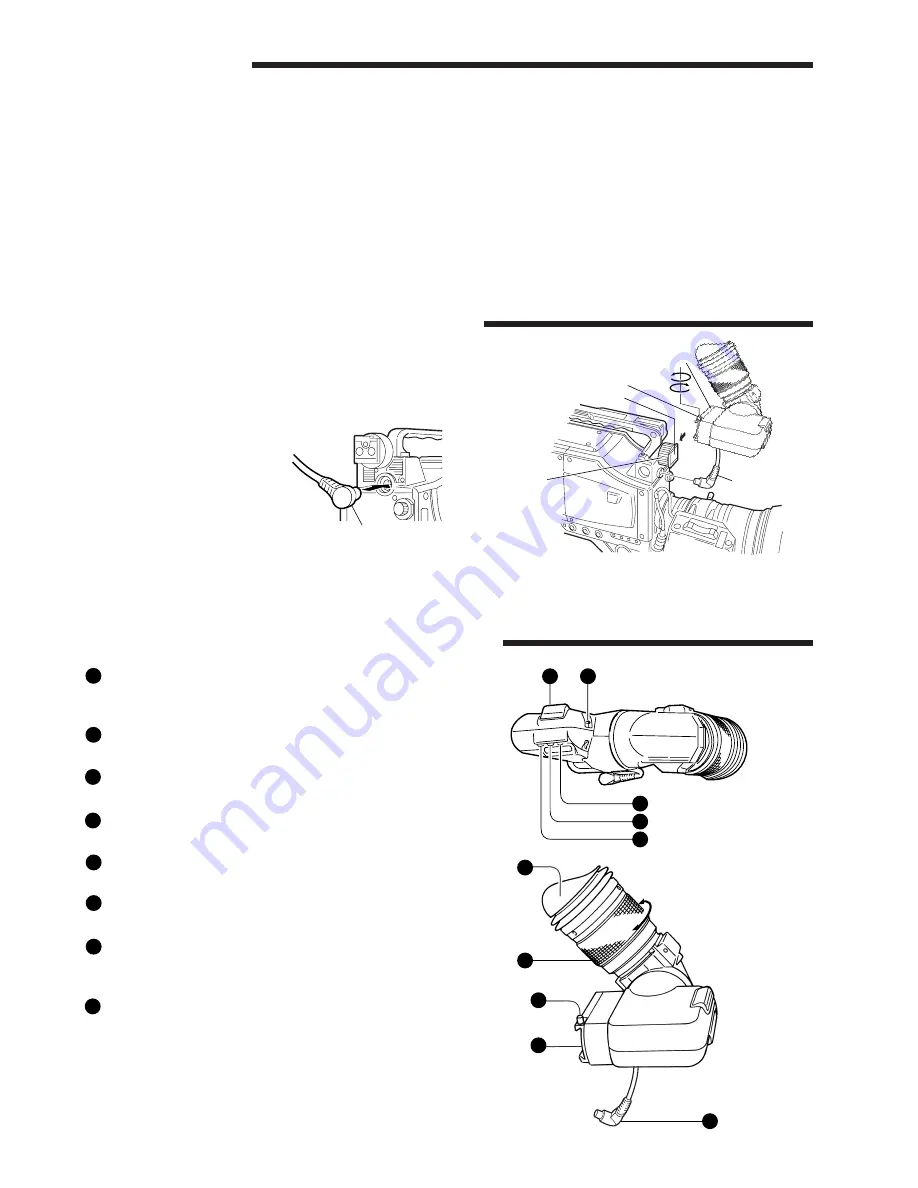
VIEWFINDER ATTACHING/DETACHING
3.
Connector
1.
Loosen the stopper screw.
2.
Attach the viewfinder with its shoe aligned with the mount base.
3.
Connect the Connector.
• Make sure to connect this
in the correct direction.
4.
Tighten the stopper screw.
5.
Tighten the ring.
CONTROLS, INDICATORS, CONNECTORS
1
2
3
7
6
5
4
8
STOPPER SCREW
This stopper screw prevents the viewfinder from coming
off the camera.
VIEWFINDER SHOE
Attaches to the Viewfinder mount base on camera.
CONNECTOR
Connect to camera socket.
CONTRAST
Controls the level of viewfinder contrast.
BRIGHT
Controls the level of viewfinder brightness.
PEAKING
Controls the level of viewfinder peaking.
TALLY SWITCH
Set this switch to off if you do not want to inform the
subjects by the tally light that they are being recorded.
TALLY LIGHT
Lights when recording is in progress.
3
10
1
2
9
8
7
5
4
6
3


