background image

3-7

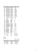
Electrical parts list

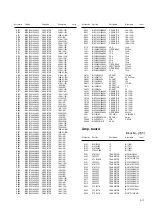
Main board

Block No. [0][1]

Symbol No.

Part No.

Part Name

Description

Local

IC401

S3C825A

IC

BI118131

IC402

PST3429UL

IC

BI117161

IC501

BA4558F

IC

BI103952 OP/AMP

IC601

BD3881FV

IC

BI112721

Q401

DTC114YK

TRANSISTOR

BI2DTC114YKA011

Q402

2SC3052

TRANSISTOR

BI2SC3052FA013V

Q403

2SC3052

TRANSISTOR

BI2SC3052FA013V

Q404

2SC3052

TRANSISTOR

BI2SC3052FA013V

Q405

2SA1980G

TRANSISTOR

BI2SA1980GP000
V

Q501

KTC3199GR

TRANSISTOR

BI2KTC3199GP00
0

Q502

KTC3199GR

TRANSISTOR

BI2KTC3199GP00
0

Q602

2SC3052

TRANSISTOR

BI2SC3052FA013V

Q603

2SC3052

TRANSISTOR

BI2SC3052FA013V

Q683

KTA1267GR

TRANSISTOR

BI2KTA1267GP000

Q684

2SC3052

TRANSISTOR

BI2SC3052FA013V

D401

1SS133

FR DIODE

BI31SS133M000V
7

D402

1SS133

FR DIODE

BI31SS133M000V
7

D403

1SS133

FR DIODE

BI31SS133M000V
7

D404

1SS133

FR DIODE

BI31SS133M000V
7

D405

1SS133

FR DIODE

BI31SS133M000V
7

D406

1SS133

FR DIODE

BI31SS133M000V
7

D407

1SS133

FR DIODE

BI31SS133M000V
7

D501

1SS133

FR DIODE

BI31SS133M000V
7

D502

1SS133

FR DIODE

BI31SS133M000V
7

D601

1SS355

DIODE

BI31SS355A0077

D602

1SS355

DIODE

BI31SS355A0077

D603

1SS133

FR DIODE

BI31SS133M000V
7

C401

BICC104500ZA043

C CAPACITOR

0.1uF 50V

C402

BICE107160MP015

E CAPACITOR

100uF 16V

C403

BICC150500JA041

C CAPACITOR

15pF 50V

C404

BICC330500JA041

C CAPACITOR

33pF 50V

C405

BICC101500JA041

C CAPACITOR

100pF 50V

C406

BICC104500ZA043

C CAPACITOR

0.1uF 50V

C407

BICC104500ZA043

C CAPACITOR

0.1uF 50V

C408

BICE226160MP015

E CAPACITOR

22uF 16V

C409

BICC104500ZA043

C CAPACITOR

0.1uF 50V

C411

BICC220500JA041

C CAPACITOR

22pF 50V

C412

BICC220500JA041

C CAPACITOR

22pF 50V

C413

BICE477063MP015

E CAPACITOR

470uF 6.3V

C414

BICE477063MP015

E CAPACITOR

470uF 6.3V

C415

BICE107100MP015

E CAPACITOR

100uF 10V

C416

BICC222500KA042

C CAPACITOR

2200pF 50V

C417

BICC104500KA042

C CAPACITOR

0.1uF 50V

C421

BICC104500ZA043

C CAPACITOR

0.1uF 50V

C422

BICC330500JA041

C CAPACITOR

33pF 50V

C423

BICC330500JA041

C CAPACITOR

33pF 50V

C424

BICC330500JA041

C CAPACITOR

33pF 50V

C425

BICC330500JA041

C CAPACITOR

33pF 50V

C426

BICC220500JA041

C CAPACITOR

22pF 50V

C501

BICE107160MP015

E CAPACITOR

100uF 16V

C502

BICE107160MP015

E CAPACITOR

100uF 16V

C503

BICC104500ZA043

C CAPACITOR

0.1uF 50V

C504

BICC104500ZA043

C CAPACITOR

0.1uF 50V

C505

BICM124101KP015

M CAPACITOR

0.12uF 100V

C506

BICM124101KP015

M CAPACITOR

0.12uF 100V

C507

BICE107160MP015

E CAPACITOR

100uF 16V

C508

BICE107160MP015

E CAPACITOR

100uF 16V

C509

BICE475500MP015

E CAPACITOR

4.7uF 50V

C510

BICE475500MP015

E CAPACITOR

4.7uF 50V

C511

BICE475500MP015

E CAPACITOR

4.7uF 50V

C609

BICC561500JA041

C CAPACITOR

560pF 50V

C610

BICC561500JA041

C CAPACITOR

560pF 50V

C611

BICE225500MP015

E CAPACITOR

2.2uF 50V

C612

BICE225500MP015

E CAPACITOR

2.2uF 50V

C631

BICC822500KA042

C CAPACITOR

8200pF 50V

C632

BICC822500KA042

C CAPACITOR

8200pF 50V

C633

BICC101500JA041

C CAPACITOR

100pF 50V

C634

BICC104500ZA043

C CAPACITOR

0.1uF 50V

C635

BICC104500ZA043

C CAPACITOR

0.1uF 50V

C636

BICE227100MP015

E CAPACITOR

220uF 10V

C637

BICE107100MP015

E CAPACITOR

100uF 10V

C641

BICM124101KP015

M CAPACITOR

0.12uF 100V

C642

BICM124101KP015

M CAPACITOR

0.12uF 100V

C643

BICE104500MP015

E CAPACITOR

0.1uF 50V

C644

BICE474500MP015

E CAPACITOR

0.47uF 50V

C645

BICC683160KA042

C CAPACITOR

0.068uF 16V

C646

BICC683160KA042

C CAPACITOR

0.068uF 16V

C647

BICE474500MP015

E CAPACITOR

0.47uF 50V

C648

BICE104500MP015

E CAPACITOR

0.1uF 50V

C649

BICC222500KA042

C CAPACITOR

2200pF 50V

C650

BICC222500KA042

C CAPACITOR

2200pF 50V

C661

BICC222500KA042

C CAPACITOR

2200pF 50V

C662

BICC222500KA042

C CAPACITOR

2200pF 50V

C663

BICC104500ZA043

C CAPACITOR

0.1uF 50V

C671

BICE225500MP015

E CAPACITOR

2.2uF 50V

C672

BICE225500MP015

E CAPACITOR

2.2uF 50V

C673

BICC222500KA042

C CAPACITOR

2200pF 50V

C674

BICC222500KA042

C CAPACITOR

2200pF 50V

C675

BICE225500MP015

E CAPACITOR

2.2uF 50V

C676

BICE225500MP015

E CAPACITOR

2.2uF 50V

C681

BICC102500KA042

C CAPACITOR

1000pF 50V

C682

BICC102500KA042

C CAPACITOR

1000pF 50V

C683

BICE476160MP015

E CAPACITOR

47uF 16V

C684

BICC101500JA041

C CAPACITOR

100pF 50V

C685

BICC101500JA041

C CAPACITOR

100pF 50V

C686

BICC101500JA041

C CAPACITOR

100pF 50V

C689

BICC101500JA041

C CAPACITOR

100pF 50V

C690

BICC101500JA041

C CAPACITOR

100pF 50V

R401

BIRC1020085M000

C RESISTOR

1K

Ω

 1/8W

R402

BIRC0000105A005

C RESISTOR

0

Ω

 1/10W

R403

BIRC1530105A005

C RESISTOR

15K

Ω

 1/10W

R405

BIRC1030085N000

C RESISTOR

10K

Ω

  1/8W

R406

BIRC1020105A005

C RESISTOR

1K

Ω

 1/10W

R407

BIRC1020105A005

C RESISTOR

1K

Ω

 1/10W

R408

BIRC1030105A005

C RESISTOR

10K

Ω

 1/10W

R409

BIRC4710105A005

C RESISTOR

470

Ω

 1/10W

R410

BIRC1020105A005

C RESISTOR

1K

Ω

 1/10W

R411

BIRC1040105A005

C RESISTOR

100K

Ω

 1/10W

R412

BIRC0000105A005

C RESISTOR

0

Ω

 1/10W

R413

BIRC2220105A005

C RESISTOR

2.2K

Ω

 1/10W

R419

BIRC1030105A005

C RESISTOR

10K

Ω

 1/10W

R420

BIRC1030105A005

C RESISTOR

10K

Ω

 1/10W

R421

BIRC1010105A005

C RESISTOR

100

Ω

 1/10W

R422

BIRC1010105A005

C RESISTOR

100

Ω

 1/10W

R423

BIRC1010105A005

C RESISTOR

100

Ω

 1/10W

R424

BIRC1010105A005

C RESISTOR

100

Ω

 1/10W

R425

BIRC1010105A005

C RESISTOR

100

Ω

 1/10W

R426

BIRC1010105A005

C RESISTOR

100

Ω

 1/10W

R427

BIRC1010105A005

C RESISTOR

100

Ω

 1/10W

R428

BIRC1010105A005

C RESISTOR

100

Ω

 1/10W

R429

BIRC1010105A005

C RESISTOR

100

Ω

 1/10W

R430

BIRC1010105A005

C RESISTOR

100

Ω

 1/10W

R431

BIRC1010105A005

C RESISTOR

100

Ω

 1/10W

R432

BIRC1010105A005

C RESISTOR

100

Ω

 1/10W

R433

BIRC1010085N000

C RESISTOR

100

Ω

  1/8W

R434

BIRC1010085N000

C RESISTOR

100

Ω

  1/8W

R435

BIRC1010085N000

C RESISTOR

100

Ω

  1/8W

R436

BIRC1010085M000

C RESISTOR

100

Ω

  1/8W

R437

BIRC1010085M000

C RESISTOR

100

Ω

  1/8W

R438

BIRC1020105A005

C RESISTOR

1K

Ω

 1/10W

R440

BIRC1010085M000

C RESISTOR

100

Ω

  1/8W

R443

BIRC1010085N000

C RESISTOR

100

Ω

  1/8W

Symbol No.

Part No.

Part Name

Description

Local

Содержание UX-S59

Страница 1: ...09 2005 6 UX S59 Lead free solder used in the board material Sn Ag Cu melting point 219 Centigrade TABLE OF CONTENTS 1 PRECAUTIONS 1 3 2 SPECIFIC SERVICE INSTRUCTIONS 1 5 3 DISASSEMBLY 1 6 4 ADJUSTMENT 1 19 5 TROUBLESHOOTING 1 19 Area suffix B U K E Continental Europe EN Northern Europe EV Eastern Europe ...

Страница 2: ...M MW tuning range Dynamic range 522 kHz 1 629 kHz CD player section 85 dB Signal to noise ratio 85 dB Wow and flutter Immeasurable General Power requirement AC 230 V 50 Hz Power consumption 125 W at operation 0 9 W on standby Dimensions approx 175 mm 232 mm 412 mm W H D Mass approx 6 6 kg Speakers Type 2 way Bass reflex Speaker units Woofer 10 cm cone 1 Tweeter 4 cm cone 1 Impedance 6 Ω Dimensions...

Страница 3: ...jack control shafts etc to be sure the product is safe to operate without danger of electrical shock Do not use a line isolation transformer during this check Plug the AC line cord directly into the AC outlet Using a Leakage Current Tester measure the leakage current from each exposed metal parts of the cabinet particular ly any exposed metal part having a return path to the chassis to a known goo...

Страница 4: ...same safety characteristics as the recommended replacement parts shown in the Parts List of the Service Manual and may create shock fire or other hazards 4 The leads in the products are routed and dressed with ties clamps tubings barriers and the like to be separated from live parts high temperature parts moving parts and or sharp edges for the prevention of electric shock and fire hazard When ser...

Страница 5: ... No MB409 1 5 SECTION 2 SPECIFIC SERVICE INSTRUCTIONS This service manual does not describe SPECIFIC SERVICE INSTRUCTIONS ...

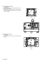
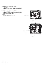
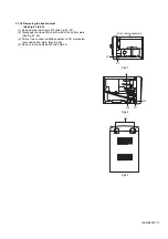
Страница 6: ...e the right plate left plate top cover 1 Remove the two screws A from the heat sink between AMP IC 2 Remove the solder fixing the AMP IC 3 1 3 Replacing the THMS RES See Fig 2 Prior to performing the following procedure remove right plate left plate top cover 1 Remove the one screw B from head sink 2 Remove the solder fixing THMS RES 3 1 4 Replacing the transistor See Fig 2 1 Remove the one screw ...

Страница 7: ...plate Fig 4 3 1 7 Removing the right plate See Fig 5 1 Remove the two screws F from right plate 2 Take off right plate from main body Fig 5 3 1 8 Removing the left plate See Fig 6 1 Remove the two screws G from left plate 2 Take off left plate from main body Fig 6 SPEAKERS IMPEDANCE 6 16 E E E E Transformaer cover F Right plate G Left plate ...

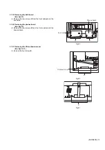
Страница 8: ... Fig 7 8 2 Disengage the claws H2 on both side of the front cabinet See Fig 7 8 3 Rotate top cover and let s away from main body See Fig 9 Caution When you rotate top cover must to slow raise Don t to destroy the two claws of front cabinet Fig 7 Fig 8 Fig 9 H1 Top cover H2 H1 Top cover H2 ...

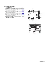
Страница 9: ... connector CN661 on main board See Fig 10 3 Disconnect the FFC cables J3 from the connector CN402 on main board See Fig 11 4 Disconnect the FFC cables J4 from the connector CN681 on main board See Fig 12 5 Remove main board from AMP board after disconnect the connector J319 and CN601 SeeFig 13 Fig 10 Fig 11 Fig 12 Fig 13 J1 J1 J2 J3 J4 J4 ...

Страница 10: ...move the two screws K1 from CD mechanism cover and power board See Fig 14 2 Disconnect the wire K2 from the connector CN102 on the AMP board See Fig 15 3 Disconnect the two wire K3 from the connector CN901 and CN902 See Fig 16 Fig 14 Fig 15 Fig 16 Power board K1 K2 K3 ...

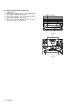
Страница 11: ...ottom plate See Fig 17 2 Disconnect the wire I2 from the connector CN105 on the AMP board See Fig 18 Fig 17 Fig 18 3 1 13 Removing the fan See Fig 19 1 Removing the four screws M2 3 1 14 Removing the tuner pack See Fig 19 1 Removing the two screws M1 Fig 19 I1 Rear plate assembly I2 m1 m2 m2 Fan m2 m2 m1 Tuner pack ...

Страница 12: ...hree screws N1 of the AMP board between CD mechanism cover See Fig 20 2 Removing the two screws N2 of the AMP board between CD mechanism cover See Fig 21 3 Disconnect the two wires N3 from the connector CN101 and CN204 on the AMP board See Fig 22 Fig 20 Fig 21 Fig 22 N1 N2 N2 N2 ...

Страница 13: ...screws O1 See Fig 23 24 2 Disengage the claws O2 on both side of the bottom plate See Fig 23 24 3 Pull out two connect wire O4 separate on CD mechanism cover and bottom plate See Fig 24 4 Remove the two screws O3 See Fig 25 Fig 23 Fig 24 Fig 25 Front cabine assembly O1 O2 O4 O4 O1 O2 O3 ...

Страница 14: ... the key board See Fig 26 2 Hand hold volume knob Use the flat screw driver prop up volume knob bottom surface and let s move out of the Front cabinet See Fig 27 Fig 26 Fig 27 3 1 18 Removing the key board See Fig 28 1 Remove the eight screws P from the front cabinet and the key board Fig 28 Volume knob Key board P P P ...

Страница 15: ... front cabinet and the aux board 3 1 20 Removing the phones board See Fig 29 1 Remove the two screws R from the front cabinet and the phones board Fig 29 3 1 21 Removing the CD mechanism cover See Fig 30 31 1 Remove the four screws S Fig 30 Fig 31 Aux board Phones board Q R CD Mech Cover S S ...

Страница 16: ...e two screws T from the CD mechanism F and CD mechanism assembly See Fig 32 2 Remove the two screws T from the CD mechanism B and CD mechanism assembly See Fig 33 3 Take out CD mechanism assembly from the CD mecha nism F between the CD mechanism B Fig 32 Fig 33 CD MECH Assembly T T ...

Страница 17: ...N701 on the CD board See Fig 34 3 Disconnect the FFC cable W3 from the connector JW756 on the CD board See Fig 34 4 Disconnect the FFC cable W4 from the connector CN802 on the CD board See Fig 34 5 Disconnect the FFC cable W5 from the connector CN801 on the CD board See Fig 34 6 Disconnect the wire W8 from connector of the CD mecha nism CMS See Fig 35 Fig 34 Fig 35 W1 W1 W2 W3 W5 W4 W6W7 W8 ...

Страница 18: ...s X from the CD mechanism hold er and the CD mechanism 3 1 25 Removing the CD mechanism CMS See Fig 36 37 1 Remove the four screws Y from the CD mechanism holder 2 Take out CD mechanism CMS Caution Don t touch laser camera lens and PCB Fig 36 Fig 37 Y X CD MECH HOLDER X Y Y CD MECHCMISM CMS ...

Страница 19: ... No MB409 1 19 SECTION 4 ADJUSTMENT This service manual does not describe ADJUSTMENT SECTION 5 TROUBLESHOOTING This service manual does not describe TROUBLESHOOTING ...

Страница 20: ... No MB409 AV MULTIMEDIA COMPANY AUDIO VIDEO SYSTEMS CATEGORY 10 1 1chome Ohwatari machi Maebashi city 371 8543 Japan Victor Company of Japan Limited VPT Printed in Japan ...

Страница 21: ...xploded view of general assembly and parts list Block No M1 CD mechanism assembly and parts list Block No MB Electrical parts list Block No 01 06 Packing materials and accessories parts list Block No M3 UX S59 3 2 3 5 3 7 3 14 Area suffix B U K E Continental Europe EN Northern Europe EV Eastern Europe MB409 ...

Страница 22: ...board 9 8 7 10 6 5 11 12 65 1 4 3 2 64 62 62 62 65 2 2 53 56 56 56 52 51 57 58 50 50 59 60 60 2 2 60 2 2 47 48 49 46 16 13 14 15 13 19 20 21 2 2 2 2 2 2 2 18 17 17 23 66 F901 41 41 28 41 26 39 41 Block No M M M 1 A B B Dusb board CD board Dhp board Front board 54 67 ...

Страница 23: ...3 3 52 51 41 41 41 41 64 64 45 53 51 53 41 27 26 1 39 1 41 41 30 31 31 39 39 29 25 33 34 36 37 38 38 39 39 39 39 38 38 42 17 17 41 38 38 40 38 38 38 38 38 41 43 43 44 A Amp board Main board 54 ...

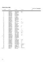
Страница 24: ...101 HEATSINK 30 BI2029330101W1 HEAT RES BKT 31 BIBT0006091 TAPPING SCREW x2 33 BI2029000101W1 CD MECH COVER 34 BIZ25094901VV TUNER PACK 36 BI2400241V DC FAN DC12V 37 BI2028950301W1 REAR PLATE 38 BIRM000603S3 TAPPING SCREW x12 39 BIRT000617B3 TAPPING SCREW x11 40 BI1080790101V1 TRANS COVER 41 BIBT000604S3 TAPPING SCREW x14 42 BI2028970101W1 RIGHT PLATE 43 BIPMW001101S3 TAPPING SCREW x4 44 BI2110410...

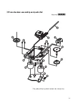
Страница 25: ...3 5 CD mechanism assembly and parts list Block No M M M B The parts without symbol number are not service 1 8 11 3 9 4 5 2 7 10 6 10 14 12 13 ...

Страница 26: ...0601G GEAR COVER 3 BIAJ6600601D GEAR A 4 BIAJ6600601B GEAR B 5 BIAJ6600601F GEAR C 6 BIAJ7000601A SHAFT 7 BISOHAAN PICK UP 8 BIAJ3100601B SPINDLE MOTOR 9 BIAJ3100601A FEED MOTOR 10 BIAJ6000601D SCREW M2XL3 x4 11 BI3409000174 LEAF SWITCH 12 BIAJ4100601E SUB PCB 13 BIAJ3700601A CONNECTOR 14 BIAJ7500601K TURN TABLE ...

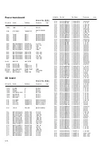
Страница 27: ...F 50V C632 BICC822500KA042 C CAPACITOR 8200pF 50V C633 BICC101500JA041 C CAPACITOR 100pF 50V C634 BICC104500ZA043 C CAPACITOR 0 1uF 50V C635 BICC104500ZA043 C CAPACITOR 0 1uF 50V C636 BICE227100MP015 E CAPACITOR 220uF 10V C637 BICE107100MP015 E CAPACITOR 100uF 10V C641 BICM124101KP015 M CAPACITOR 0 12uF 100V C642 BICM124101KP015 M CAPACITOR 0 12uF 100V C643 BICE104500MP015 E CAPACITOR 0 1uF 50V C6...

Страница 28: ...5630105A005 C RESISTOR 56KΩ 1 10W R632 BIRC5630105A005 C RESISTOR 56KΩ 1 10W R633 BIRC1030105A005 C RESISTOR 10KΩ 1 10W R635 BIRC4720105A005 C RESISTOR 4 7KΩ 1 10W R636 BIRC4720085M000 C RESISTOR 4 7KΩ 1 8W R637 BIRC2210045M000 C RESISTOR 220Ω 1 4W R638 BIRC2210045M000 C RESISTOR 220Ω 1 4W R641 BIRC1020105A005 C RESISTOR 1KΩ 1 10W R642 BIRC1020085M000 C RESISTOR 1KΩ 1 8W R643 BIRC2020105A005 C RES...

Страница 29: ...W R381 BIRC1020105A005 C RESISTOR 1KΩ 1 10W R382 BIRC1010105A005 C RESISTOR 100Ω 1 10W R383 BIRC1010105A005 C RESISTOR 100Ω 1 10W R384 BIRC1010105A005 C RESISTOR 100Ω 1 10W R386 BIRC4730105A005 C RESISTOR 47KΩ 1 10W Symbol No Part No Part Name Description Local R391 BIRC2020105A005 C RESISTOR 2KΩ 1 10W R392 BIRC3020105A005 C RESISTOR 3KΩ 1 10W R393 BIRC3920105A005 C RESISTOR 3 9KΩ 1 10W R394 BIRC6...

Страница 30: ...041 C CAPACITOR 1000pF 50V C730 BICC222500KA042 C CAPACITOR 2200pF 50V C731 BICC333250KA042 C CAPACITOR 0 033uF 25V C732 BICC10450KA042 C CAPACITOR 0 1uF 50V C733 BICC10450KA042 C CAPACITOR 0 1uF 50V C734 BICC101500JA041 C CAPACITOR 100pF 50V C735 BICC101500JA041 C CAPACITOR 100pF 50V C736 BICC101500JA041 C CAPACITOR 100pF 50V C737 BICC101500JA041 C CAPACITOR 100pF 50V C738 BICC101500JA041 C CAPAC...

Страница 31: ...BIRC1210085M000 C RESISTOR 120Ω 1 8W R878 BIRC1210085M000 C RESISTOR 120Ω 1 8W R879 BIRC1210085M000 C RESISTOR 120Ω 1 8W R880 BIRC1210085M000 C RESISTOR 120Ω 1 8W R881 BIRC1210085M000 C RESISTOR 120Ω 1 8W R882 BIRC1030105A005 C RESISTOR 10KΩ 1 10W R883 BIRC1030105A005 C RESISTOR 10KΩ 1 10W R884 BIRC1020085M000 C RESISTOR 1KΩ 1 8W R885 BIRC1020085M000 C RESISTOR 1KΩ 1 8W R886 BIRC1020105A005 C RESI...

Страница 32: ...ICC221500JA041 C CAPACITOR 220pF 50V C213 BICE107500MP015 E CAPACITOR 100uF 50V C214 BICE107500MP015 E CAPACITOR 100uF 50V C215 BICE476500MP015 CAPACITOR 47uF 50V C216 BICE476500MP015 CAPACITOR 47uF 50V C237 BICC104500KA042 C CAPACITOR 0 1uF 50V C238 BICC104500KA042 C CAPACITOR 0 1uF 50V C239 BICC104500KA042 C CAPACITOR 0 1uF 50V C240 BICC104500KA042 C CAPACITOR 0 1uF 50V C241 BICE106500MP015 E CA...

Страница 33: ...V SOCKET 2P CN201 BI12S150028V SOCKET 15P CN202 BI12S80058V SOCKET 8 P CN204 BI12S40047V SOCKET 4P JR101 BIRC0000085A003 C RESISTOR 0Ω 1 8W JR102 BIRC0000085A003 C RESISTOR 0Ω 1 8W JR103 BIRC0000085A003 C RESISTOR 0Ω 1 8W JR104 BIRC0000085A003 C RESISTOR 0Ω 1 8W JR105 BIRC0000085A003 C RESISTOR 0Ω 1 8W JR106 BIRC0000085A003 C RESISTOR 0Ω 1 8W JR107 BIRC0000085A003 C RESISTOR 0Ω 1 8W P103 BI11A050M...

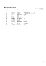
Страница 34: ...g materials and accessories parts list P6 P9 P10 P8 P2 P2 P7 P1 A7 A1A2 A1A2A3 A4 A5 A6 Block No M M M 3 No additional supplemental order of WARRANTY CARDs are available E EN EV version only B version P3 P5 P4 A8 ...

Страница 35: ...BI400083291001 REGISTRATION CARD B A 4 BATTERY x2 A 5 BIAN01281V AM LOOP ANT A 6 BIAN01022V ANT WIRE FM A 7 BI643UXS59020 REMOTE CONTROL A 8 BI644UXS59202S SPEAKER SYSTEM x2 P 1 BI430001843000 CARTON P 2 BI470011031001W POLY BAG I B P 3 BI470011057001W POLY BAG ANT LOOP P 4 BI450012012000 TOP CUSHION Speaker Box P 5 BI450012013000 BOTTOM CUSHION Speaker Box P 6 BI450012031000W FRONT CUSHION UNIT P...

Страница 36: ...t boards 2 1 2 2 2 6 to 11 CD ROM No SML200507 MICRO COMPONENT SYSTEM No MB409SCH 2005 7 COPYRIGHT 2005 Victor Company of Japan Limited Lead free solder used in the board material Sn Ag Cu melting point 219 Centigrade Area suffix B U K E Continental Europe EN Northern Europe EV Eastern Europe ...

Страница 37: ...ponent parts appearing on the silk screen printed side parts side of the PWB diagrams the parts that are printed over with black such as the resistor diode and ICP or identified by the mark nearby are critical for safety ...

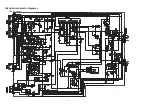
Страница 38: ...2 1 Block diagram ...

Страница 39: ...2 2 Standard schematic diagrams Amp section ...

Страница 40: ...2 3 Micon section ...

Страница 41: ...2 4 CD section ...

Страница 42: ...2 5 Parts are safety assurance parts When replacing those parts make sure to use the specified one Display and Primary section ...

Страница 43: ...2 6 Printed circuit boards Lead free solder used in the board material Sn Ag Cu melting point 219 Centigrade Main board forward side ...

Страница 44: ...2 7 Lead free solder used in the board material Sn Ag Cu melting point 219 Centigrade Main board reverse side ...

Страница 45: ...2 8 Lead free solder used in the board material Sn Ag Cu melting point 219 Centigrade Amp board reverse side forward side ...

Страница 46: ...2 9 Front board forward side forward side Lead free solder used in the board material Sn Ag Cu melting point 219 Centigrade ...

Страница 47: ...2 10 CD board Lead free solder used in the board material Sn Ag Cu melting point 219 Centigrade forward side reverse side ...

Страница 48: ...2 11 Trans board Lead free solder used in the board material Sn Ag Cu melting point 219 Centigrade ...

Страница 49: ...Victor Company of Japan Limited No MB409SCH Printed in Japan VPT AV MULTIMEDIA COMPANY AUDIO VIDEO SYSTEMS CATEGORY 10 1 1chome Ohwatari machi Maebashi city 371 8543 Japan ...
Отзывы: