


3-8
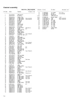
Electrical parts list
Main board
Block No. [0][1][0][0]
Symbol No.
Part No.
Part Name
Description Local
IC300
LA4663
POWER IC
IC301
HA17558A
IC
IC302
LC75342
IC
IC601
AN22000A-W
IC
IC602
LA6541-X
IC
IC603
MN662748RPMFA
IC
IC604
KIA78S05P-T
IC
Q601
KTA1271/OY/-T
TRANSISTOR
Q1150
2SC3576-JVC-T
TRANSISTOR
Q1400
2SC2785/FE/-T
TRANSISTOR
Q2150
2SC3576-JVC-T
TRANSISTOR
Q2400
2SC2785/FE/-T
TRANSISTOR
Q3110
2SC3576-JVC-T
TRANSISTOR
Q3111
KRC111M-T
TRANSISTOR
Q3150
KRA101M-T
TRANSISTOR
Q3151
KRC102M-T
DIGI TRANSISTOR
Q9001
KTA1046/Y/
TRANSISTOR
Q9002
2SC2785/FE/-T
TRANSISTOR
Q9003
2SA1175/FE/-T
TRANSISTOR
Q9004
KRC114M-T
TRANSISTOR
Q9005
KRA114M-T
TRANSISTOR
Q9006
2SC2785/FE/-T
TRANSISTOR
Q9070
2SC3576-JVC-T
TRANSISTOR
Q9201
KTB772/Y/
TRANSISTOR
Q9202
2SC2785/FE/-T
TRANSISTOR
Q9301
KTA1267/YG/-T
TRANSISTOR
Q9302
2SC2785/FE/-T
TRANSISTOR
D661
1SS133-T2
DIODE
D662
1SS133-T2
DIODE
D901
6A10E2
SI DIODE
D902
6A10E2
SI DIODE
D903
6A10E2
SI DIODE
D904
6A10E2
SI DIODE
D905
6A10E2
SI DIODE
D3150
MTZJ5.1C-T2
Z DIODE
D3151
1SS133-T2
DIODE
D3153
1SS133-T2
DIODE
D3400
1SS133-T2
DIODE
D3401
1SS133-T2
DIODE
D3402
1SS133-T2
DIODE
D3403
1SS133-T2
DIODE
D3504
1SS133-T2
DIODE
D3505
1SS133-T2
DIODE
D9001
1SS133-T2
DIODE
D9002
MTZJ8.2C-T2
Z DIODE
D9020
MTZJ5.6C-T2
Z DIODE
D9201
MTZJ4.3B-T2
Z DIODE
D9302
1SS133-T2
DIODE
D9303
1SS133-T2
DIODE
D9501
1SS133-T2
DIODE
D9502
1N4003S-T5
SI DIODE
C602
QCSB1HJ-560Y
C CAPACITOR
56pF 50V J
C604
QEKC1AM-107Z
E CAPACITOR
100uF 10V M
C605
QETN1EM-106Z
E CAPACITOR
10uF 25V M
C606
QFVF1HJ-823Z
MF CAPACITOR
0.082uF 50V J
C608
QETN1HM-105Z
E CAPACITOR
1uF 50V M
C610
QFVF1HJ-393Z
MF CAPACITOR
0.039uF 50V J
C611
QCBB1HK-103Y
C CAPACITOR
0.01uF 50V K
C612
QDXB1CM-272Y
C CAPACITOR
2700pF 16V M
C613
QCBB1HK-331Y
C CAPACITOR
330pF 50V K
C614
QCZ0313-105Z
C CAPACITOR
1uF 25V Z
C615
QDVB1EZ-223Y
C CAPACITOR
0.022uF 25V Z
C616
QDVB1EZ-223Y
C CAPACITOR
0.022uF 25V Z
C617
QCSB1HK-3R3Y
C CAPACITOR
3.3pF 50V K
C618
QFVF1HJ-104Z
MF CAPACITOR
0.1uF 50V J
C619
QCBB1HK-561Y
C CAPACITOR
560pF 50V K
C620
QCBB1HK-101Y
C CAPACITOR
100pF 50V K
C622
QFLC1HJ-223Z
M CAPACITOR
0.022uF 50V J
C623
QFVF1HJ-563Z
MF CAPACITOR
0.056uF 50V J
C624
QFLC1HJ-223Z
M CAPACITOR
0.022uF 50V J
C625
QDXB1CM-222Y
C CAPACITOR
2200pF 16V M
C628
QDX31EM-473Z
C CAPACITOR
0.047uF 25V M
C629
QETN1AM-227Z
E CAPACITOR
220uF 10V M
C631
QETN1AM-477Z
E CAPACITOR
470uF 10V M
C632
QEKC1AM-107Z
E CAPACITOR
100uF 10V M
C633
QCBB1HK-391Y
C CAPACITOR
390pF 50V K
C634
QCBB1HK-391Y
C CAPACITOR
390pF 50V K
C635
QCBB1HK-391Y
C CAPACITOR
390pF 50V K
C636
QCBB1HK-391Y
C CAPACITOR
390pF 50V K
C638
QFVF1HJ-104Z
MF CAPACITOR
0.1uF 50V J
C641
QCZ0313-105Z
C CAPACITOR
1uF 25V Z
C642
QCBB1HK-103Y
C CAPACITOR
0.01uF 50V K
C643
QEQ61HM-225Z
E CAPACITOR
2.2uF 50V M
C644
QFN31HJ-153Z
M CAPACITOR
0.015uF 50V J
C645
QEQ61HM-225Z
E CAPACITOR
2.2uF 50V M
C651
QCSB1HJ-120Y
C CAPACITOR
12pF 50V J
C652
QCSB1HJ-150Y
C CAPACITOR
15pF 50V J
C653
QDVB1EZ-223Y
C CAPACITOR
0.022uF 25V Z
C655
QCZ0202-155Z
C CAPACITOR
1.5uF 25V Z
C661
QCBB1HK-471Y
C CAPACITOR
470pF 50V K
C662
QDVB1EZ-223Y
C CAPACITOR
0.022uF 25V Z
C663
QFLC1HJ-223Z
M CAPACITOR
0.022uF 50V J
C664
QDVB1EZ-223Y
C CAPACITOR
0.022uF 25V Z
C665
QFVF1HJ-334Z
MF CAPACITOR
0.33uF 50V J
C668
QETN0JM-477Z
E CAPACITOR
470uF 6.3V M
C669
QETN0JM-477Z
E CAPACITOR
470uF 6.3V M
C670
QETN1AM-107Z
E CAPACITOR
100uF 10V M
C671
QDXB1CM-222Y
C CAPACITOR
2200pF 16V M
C672
QDXB1CM-222Y
C CAPACITOR
2200pF 16V M
C673
QETN1AM-477Z
E CAPACITOR
470uF 10V M
C674
QDVB1EZ-223Y
C CAPACITOR
0.022uF 25V Z
C675
QDGB1HK-102Y
C CAPACITOR
1000pF 50V K
C676
QDGB1HK-102Y
C CAPACITOR
1000pF 50V K
C677
QDVB1EZ-223Y
C CAPACITOR
0.022uF 25V Z
C691
QCBB1HK-151Y
C CAPACITOR
150pF 50V K
C692
QCBB1HK-151Y
C CAPACITOR
150pF 50V K
C693
QCBB1HK-151Y
C CAPACITOR
150pF 50V K
C694
QCBB1HK-101Y
C CAPACITOR
100pF 50V K
C695
QFVF1HJ-334Z
MF CAPACITOR
0.33uF 50V J
C901
QFLA1HJ-104Z
M CAPACITOR
0.1uF 50V J
C902
QFLA1HJ-104Z
M CAPACITOR
0.1uF 50V J
C903
QFLA1HJ-104Z
M CAPACITOR
0.1uF 50V J
C904
QFLA1HJ-104Z
M CAPACITOR
0.1uF 50V J
C1100
QFLC1HJ-104Z
M CAPACITOR
0.1uF 50V J
C1101
QFLC1HJ-104Z
M CAPACITOR
0.1uF 50V J
C1102
QCBB1HK-331Y
C CAPACITOR
330pF 50V K
C1103
QDXB1CM-332Y
C CAPACITOR
3300pF 16V M
C1104
QTE1V06-106Z
E CAPACITOR
10uF 35V
C1105
QCBB1HK-221Y
C CAPACITOR
220pF 50V K
C1300
QFLC1HJ-683Z
M CAPACITOR
0.068uF 50V J
C1301
QFLC1HJ-683Z
M CAPACITOR
0.068uF 50V J
C1302
QTE1V06-106Z
E CAPACITOR
10uF 35V
C1303
QFVJ1HJ-334Z
MF CAPACITOR
0.33uF 50V J
C1502
QETN1HM-475Z
E CAPACITOR
4.7uF 50V M
C1503
QTE1V06-106Z
E CAPACITOR
10uF 35V
C1504
QFVF1HJ-104Z
MF CAPACITOR
0.1uF 50V J
C1505
QFVF1HJ-104Z
MF CAPACITOR
0.1uF 50V J
C1506
QFLC1HJ-272Z
M CAPACITOR
2700pF 50V J
C1507
QETN1HM-475Z
E CAPACITOR
4.7uF 50V M
C1508
QETN1HM-475Z
E CAPACITOR
4.7uF 50V M
C1510
QETN1EM-106Z
E CAPACITOR
10uF 25V M
C1600
QCBB1HK-221Y
C CAPACITOR
220pF 50V K
C2100
QFLC1HJ-104Z
M CAPACITOR
0.1uF 50V J
C2101
QFLA1HJ-104Z
M CAPACITOR
0.1uF 50V J
C2102
QCBB1HK-331Y
C CAPACITOR
330pF 50V K
C2103
QDXB1CM-332Y
C CAPACITOR
3300pF 16V M
C2104
QTE1V06-106Z
E CAPACITOR
10uF 35V
C2105
QCBB1HK-221Y
C CAPACITOR
220pF 50V K
C2300
QFLC1HJ-683Z
M CAPACITOR
0.068uF 50V J
C2301
QFLC1HJ-683Z
M CAPACITOR
0.068uF 50V J
C2302
QTE1V06-106Z
E CAPACITOR
10uF 35V
C2303
QFVJ1HJ-334Z
MF CAPACITOR
0.33uF 50V J
C2502
QETN1HM-475Z
E CAPACITOR
4.7uF 50V M
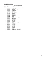
Symbol No.
Part No.
Part Name
Description Local
Содержание UX-H35
Страница 25: ... No MB053 1 25 ...
Страница 39: ... M E M O ...


