background image

ENGLISH

PAL

VOLUME

:

20

PHASE

:

00

+

Items

                   VOLUME/SELECT button

+

CHROMA

lighter

deeper

(Chroma)

PHASE

reddish

greenish

(Phase)

CONTRAST

lower

higher

(Contrast)

BRIGHT

darker

brighter

(Brightness)

STATUS indication
(PAL or NTSC)

00 ~ 50

HOW TO HANDLE BASIC
OPERATIONS

BASIC OPERATION

PICTURE ADJUSTMENT

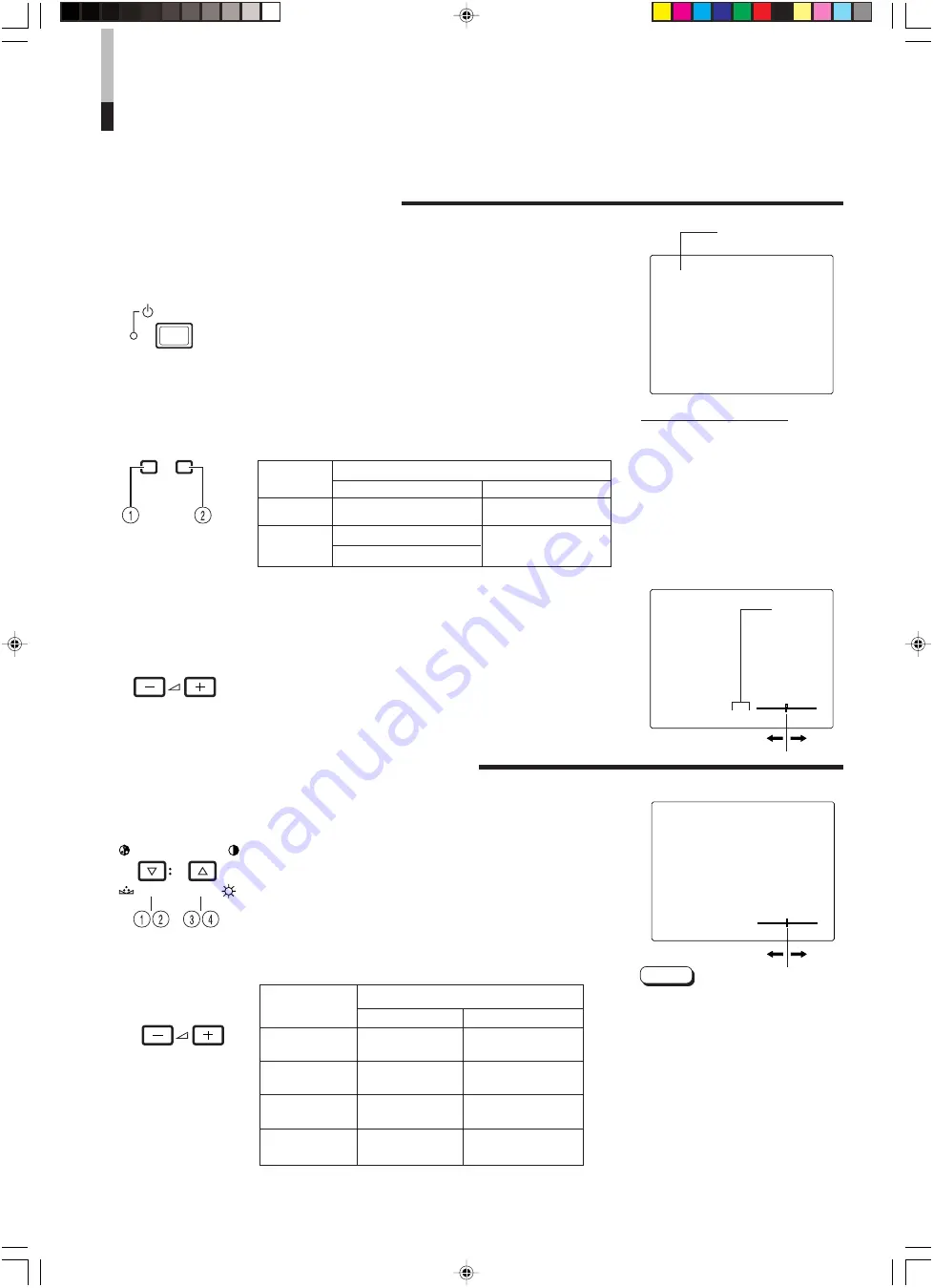
2. Press the POWER switch to turn on the power.

ON :

Power turns ON. (Power indicator: lit)
Green: The main power is ON, and the monitor’s

power is ON (in the normal operation mode).

OFF :

Power turns OFF. (Power indicator: unlit)
Orange : The main power is ON, but the monitor’s

power is OFF (in the standby mode)

Unlit

: The main power is OFF.

3. Press the INPUT SELECT buttons to choose input.

Select video/audio signals input to terminals on the rear
panel. The selected button lights in green.

4. Press the VOLUME/SELECT buttons to adjust the

speaker volume.

Press this button to display the speaker volume level on the
screen.

+ :

 The Built-in speaker volume is increased. (00 

=

 50)

– :

 The Built-in speaker volume is decreased. (50 

=

 00)

* Screen indication will disappear about 10 seconds after operating.
* The on-screen display goes off when you press MENU button.

1. Press select buttons corresponding to the item

you want to adjust.

The item you select is displayed on the screen.

1

Chroma control

: Press the CHROMA/PHASE button once.

2

Phase control

: Press the CHROMA/PHASE button twice.

3

Contrast control

: Press the CONTRAST/BRIGHT button once.

4

Brightness control : Press the CONTRAST/BRIGHT button twice.

* Pressing the CHROMA/PHASE button and CONTRAST/BRIGHT button

alternately while the item is shown on screen restores the previous status.
When no item is shown on screen, CHROMA and CONTRAST have priority.

* Screen indication will disappear about 10 seconds after operating.
* The on-screen display goes off when you press MENU button.

About the STATUS indication

 With the COLOR SYSTEM setting set

to AUTO mode, when you turn on the
power or select inputs, the colour
system indication appears for about
3 seconds on the screen while PAL or
NTSC signals are being detected.

    It does not appear when receiving a

B/W signal or when no signal is input.

   Refer to page 8 for more information

about COLOR SYSTEM setting and
page 9 for more information about
STATUS indication setting.

Notes:

 Phase control is effective only in the

NTSC colour system mode.

 Chroma control is not effective when

receiving B/W or when no signal is
input.

 When CHROMA is adjusted to “–40,”

the picture becomes less colourful.

 “NO EFFECT” is displayed (for about

3 seconds) when your selected
function has no effect.

2. Adjust with the VOLUME/SELECT buttons.

+

7

POWER

VOLUME/SELECT

CHROMA

PHASE

BRIGHT

CONTRAST

VOLUME/SELECT

VIDEO B (Y/C) terminal

1. Press the main power switch to turn on the power.

INPUT  SELECT

A

B

Terminals on the rear panel

Video signal input

Audio signal input

1

 Input A

VIDEO A terminal

AUDIO A terminal

(VIDEO)

2

 Input B

VIDEO B terminal

AUDIO B terminal

(VIDEO Y/C)

INPUT

SELECT

buttons

Note:The Y/C (S-video) terminal has priority.

 LCT1422-001A-H

07.10.25, 9:58 AM

7

Содержание TM-A170G

Страница 1: ...INSTRUCTIONS TM A170G COLOUR VIDEO MONITOR POWER CHROMA MENU INPUT SELECT PHASE TM A170 BRIGHT CONTRAST VOLUME SELECT A B LCT1422 002A H LCT1422 001A H 07 10 25 9 57 AM 1 ...

Страница 2: ... qualified service personnel under the following conditions when the power cord is frayed or the plug is damaged if liquid has been spilled into the unit if the unit has been dropped or the cabinet has been damaged when the unit exhibits a distinct change in performance Do not attempt to service this unit yourself as opening or removing covers may expose you to dangerous voltage or other hazards A...

Страница 3: ...OLS AND FEATURES 4 HOW TO HANDLE BASIC OPERATIONS 7 HOW TO USE THE MENU FUNCTIONS 8 HOW TO INITIALIZE THE SETTING 11 BASIC CONNECTION EXAMPLE 12 HOW TO USE EXTERNAL CONTROL 14 TROUBLESHOOTING 15 SPECIFICATIONS 16 LCT1422 001A H 07 10 25 9 57 AM 3 ...

Страница 4: ...DEO button INPUT SELECT A Selects the video and audio signals input to the VIDEO A and AUDIO A terminals on the rear panel The button lights when selected CONTROLS AND FEATURES FRONT VIEW Front Panel Input B VIDEOY C button INPUT SELECT B Selects the video and audio signals input to the VIDEO B or VIDEO B Y C and AUDIO B terminals on the rear panel The button lights when selected Note The VIDEO B ...

Страница 5: ...ridge connected IN Y C separated S video video signal input terminal OUT Bridge connected Y C separated S video signal output terminal REAR VIEW Rear Panel 10 11 12 13 5 Notes For corresponding audio signals use the AUDIO B terminals When both VIDEO B terminals are connected input at the same time the Y C terminal has priority Also refer to BASIC CONNECTION EXAMPLE on page 13 Audio A terminals AUD...

Страница 6: ...F When the main power is ON the power indicator on the front panel lights in orange and the monitor enters the stand by mode I ON OFF AC inlet AC IN Power input connector Connect the provided AC power cord to an AC outlet 220 V AC 50 Hz 60 Hz To AC outlet 220 V AC 50 Hz 60 Hz Power cord Connects the provided power cord 220 V AC 50 Hz 60 Hz to the AC IN connector 16 17 18 LCT1422 001A H 07 10 25 9 ...

Страница 7: ... Brightness control Press the CONTRAST BRIGHT button twice Pressing the CHROMA PHASE button and CONTRAST BRIGHT button alternately while the item is shown on screen restores the previous status When no item is shown on screen CHROMA and CONTRAST have priority Screen indication will disappear about 10 seconds after operating The on screen display goes off when you press MENU button About the STATUS...

Страница 8: ...P COLOR SYSTEM ASPECT RATIO 3 Press the VOLUME SELECT buttons to set 4 If you want to set the other menu items repeat procedures 2 and 3 5 Press the MENU button to quit 1 Selection mark 4 Indicates the menu item you select 2 Menu item Menu items you can select 3 Setting display Indicates the current settings value 4 Function display The functions of the front panel buttons 5 buttons on the left co...

Страница 9: ...value EXIT Exits the SET UP MENU screen DRV Selects DRIVE adjustment CUTO Selects CUT OFF adjustment RB Adjusts red and blue signal level RGB Adjusts red green and blue signal level DISP Turns the ON SCREEN display on or off This function is effective only in the DRIVE or CUT OFF adjustment mode Front panel Function Contents button displayed CHROMA Forwards selection mark 4 PHASE CONTRAST Reverses...

Страница 10: ...sage CONTROL LOCK ON on the screen for about 3 seconds The CONTROL LOCK function is maintained even when the power is turned off To turn off the CONTROL LOCK function while holding the MENU button press the CHROMA PHASE button Then set the CONTROL LOCK function to OFF Even when the CONTROL LOCK function is set to ON the following operations are available Power Switch operation Volume control with ...

Страница 11: ...ory set initial values 1 Press the Power switch to turn the power OFF activate the standby mode The SET UP MENU RESET screen is displayed Initial settings SET UP MENU RESET screen 2 While pressing both MENU button and CHROMA PHASE button press the Power switch to turn the power ON 3 Setting Initialization is required Initialization is not required Press the VOLUME SELECT button Initialization is c...

Страница 12: ...t the input IN and output OUT terminals on the monitor to separate video components For example if both terminals are connected to the same VCR resonance may occur except during playback This is caused by the same video signal looping between the VCRs and is not a malfunction Select the video input signal INPUT A VIDEO or INPUT B VIDEO Y C with the INPUT SELECT buttons on the front panel When both...

Страница 13: ...UDIO B VIDEO B IN OUT IN IN IN OUT OUT IN OUT Y C OUT Video Camera Video Monitor VCR Y C S video Y C S video signal cable Audio Audio signal cable Audio Audio signal cable Y C S video Y C S video signal cable Video Monitor VCR Signal Flow 13 LCT1422 001A H 07 10 25 9 58 AM 13 ...

Страница 14: ... 9 and 10 Connections Connect short circuit the 15th terminal GND to the 2nd or 10th terminals in the 3 line 15 pin D sub connector Do not connect other terminals External control switch Open circuit Closed circuit open short ASPECT RATIO 4 3 4 3 16 9 16 9 External control functions External control switch Open circuit open Closed circuit short ASPECT External control switch Open circuit Closed ci...

Страница 15: ... audio signal cable firmly See pags 12 and 13 Move the device away from the monitor until the picture stabilizes Set COLOR SYSTEM in the MENU screen to AUTO See page 8 Set each picture control to the standard setting See page 7 Move the device away from the monitor and turn the monitor s power off Wait at least 30 minutes then turn the power on again Set ASPECT RATIO in the MENU screen to 4 3 4 3 ...

Страница 16: ...TSC 0 3 V p p 75 Ω PAL bridge connection possible auto termination AUDIO A 1 line monaural RCA pin x 2 0 5 V rms high impedance bridge connection possible AUDIO B 1 line monaural RCA pin x 2 0 5 V rms high impedance bridge connection possible REMOTE Point of contact connection 1 line D sub connector 15 pin 3 line Audio power output 1 W monaural Built in speaker 8 cm round x 1 impedance of 8 Ω Envi...

Страница 17: ...ECT PHASE TM A170 BRIGHT CONTRAST VOLUME SELECT A B Dimensions Front View Side View Asterisks are used to indicate front panel dimensions Unit mm Pin No Signal 1 GND Y 2 GND C 3 Y 4 C Y C Mini DIN 4 pin terminal specification IN Y C OUT 2 1 2 1 4 3 4 3 17 LCT1422 001A H 07 10 25 9 59 AM 17 ...

Страница 18: ... 2007 Victor Company of Japan Limited 1107STH CR MT TM A170G COLOUR VIDEO MONITOR LCT1422 001A H 07 10 25 9 59 AM 18 ...

Отзывы: