


8
VOLUME/SELECT
–
+
MENU
PHASE
PHASE
CHROMA
BRIGHT CONTRAST
MENU
VOLUME/SELECT
–
+
EXIT
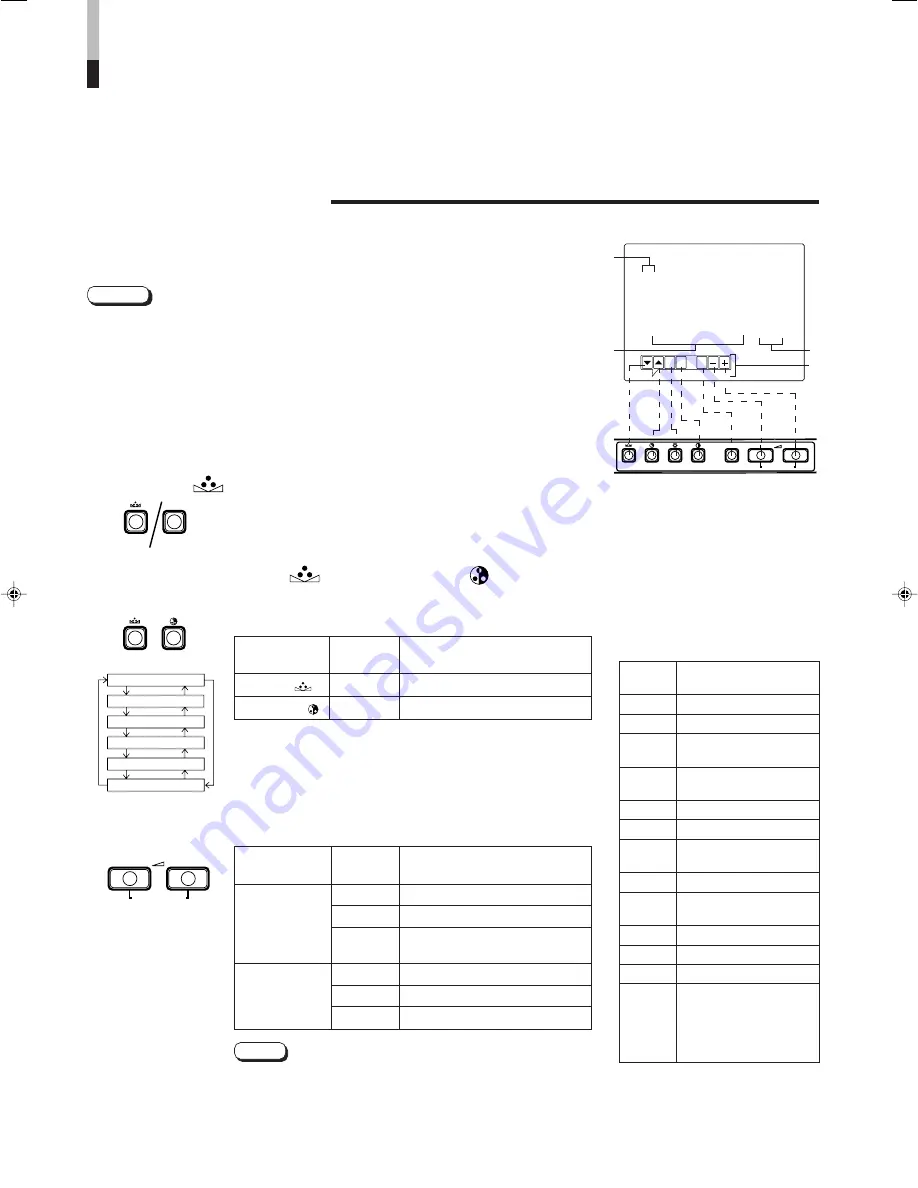
<SET–UP MENU>
‰
H. POSITION
: 00
V. POSITION
: 00
WHITE BALANCE
CONTROL LOCK
: OFF
B. P. S. LEVEL
: 10
REMOTE SELECT
: OFF
1
2
3
4
HOW TO USE THE MENU
FUNCTIONS
(cont'd)
DISPLAY AND SELECTIONS IN THE <SET-UP MENU>
MODE (SETTING)
●
H. POSITION
●
WHITE BALANCE
●
B.P.S. LEVEL
●
V. POSITION
●
CONTROL LOCK
●
REMOTE SELECT
You can set the following set-up menu items.
1. While pressing the MENU button, press the
PHASE (
) button.
The <SET-UP MENU> screen is displayed.
2. Press the PHASE (
) or CHROMA (
) button
to select the desired menu item.
A selection mark (
3
) is put next to the selected item.
H. POSITION
V. POSITION
WHITE BALANCE
CONTROL LOCK
B.P.S. LEVEL
REMOTE SELECT
3. Press the VOLUME/SELECT button to set.
●
For the WHITE BALANCE setting, select the CUT OFF or
DRIVE setting screen, then select the buttons (PHASE/
CHROMA/BRIGHT) corresponding to the function indicated
(R/G/B).
Note:
<SET-UP MENU> screen
<Front panel button>
1
Selection mark (
3
3
3
3
3
): Indicates the
menu item you select.
2
Menu item: Menu items you can
select.
3
Setting display: Indicates the
current settings (value).
4
Function display: The functions of
the front panel buttons (7 buttons on
the left.) correspond to the function
displayed.
Function
Contens
displayed
∞
Advance the menu item.
5
Reverse the menu item.
–
Lower the adjustment
value. (to the minimum)
+
Raise the adjustment
value. (to the maximum)
3
Advance the setting value.
2
Reverse the setting value.
EXIT
Exit the <SET-UP MENU>
screen (release)
DRV
Selects DRV adjustment
CUTO
Selects CUT OFF
adjustment
R
Adjusts red signal level
G
Adjusts green signal level
B
Adjusts blue signal level
DISP
Turns the ON-SCREEN
display on or off. (This
function is effective only in
the DRIVE or CUT OFF
adjustment mode.)
Front panel
Function
Contents
button
displayed
PHASE (
)
∞
Advance selection mark (
3
)
CHROMA ( )
5
Reverse selection mark (
3
)
Front panel
Function
Contents
button
displayed
+
Increase (to max. value)
3
Advance the setting value
CUTO
Selects CUT OFF setting
screen
–
Decrease (to min. value)
2
Reverse the setting value
DRV
Selects DRIVE setting screen
VOLUME/
SELECT (–)
VOLUME/
SELECT (+)
●
Parameters for H. POSITION and V. POSITION can be set separately depending on
the video input (Input A (VIDEO), Input B (VIDEO) or Input B (Y/C)) selected by the
input select buttons on the front panel.
Select the required video input with the input select buttons on the front panel in
advance.
●
WHITE BALANCE can be set individually at 6500 or 9300 for the color temperature
value.
Set COLOR TEMP. to the value 6500 or 9300 in the <MENU> screen in advance.
Notes:
PHASE
CHROMA


