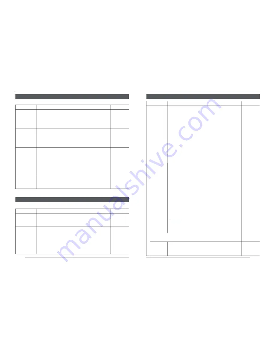
manualshive.com logo in svg
background image

E-26

Item

 Functions and set values

Initial value

V PHASE

H PHASE

SC COARSE

SC FINE

This adjusts the vertical synchronization to those of other cameras
when a selector switch for the synchronizing system on the side
is at LL. (50Hz power region only.)
When it is not set to LL, “---” will appear, disabling change
the set value.
[Set value:  –156 to 0 to 156]

This adjusts the horizontal synchronization to those of other
cameras and systems when a selector switch for the
synchronizing system on the side is at INT/GL.
When external signals are not input, “---” will appear, disabling
change the set value.
[Set values:  –16 to 0 to 16]

Coarse adjustment of the SC phase in gen-lock operation.
The SC phase can be varied by up to 90° in each direction.
Adjust with reference to another camera (or system) and
together with the SC FINE adjustment.
Adjust SC COARSE and SC FINE only after adjusting H
PHASE.
When it is not set to GL, “---” will appear, disabling change
the set value.
[Set values:  0°, 90°, 180°, 270°]

Fine adjustment of the SC phase in gen-lock operation.
When it is not set to GL, “---” will appear, disabling change
the set value.
[Set values: 0 to 255]

MENU SETTING

SYNC ADJUST Screen

This executes the setting regarding synchronization.

0

0

0

°

128

ALC SETTINGS Screen

Item

 Functions and set values

Initial value

IRIS LEVEL

AVERAGE:
PEAK

This makes automatic adjustments according to brightness.

Adjusts the brightness level of the video signal.

• To lower the brightness level ... Decrease the value
• To raise the brightness level .... Increase the value

[Set values: –5 to NORMAL to 5]

Sets the exposure detection as a ratio of the average value
and the peak value.

• AVERAGE value large: Increase the AVERAGE value

when portions other than the highlighted areas of the
screen are dark and look corrupted. (Ex. 10:0)

• PEAK value large: Increase the PEAK value when

halation occurs in the highlighted areas of the screen.
(Ex. 5:5)

[Set values: 10:0, 9:1, 8:2, 7:3, 6:4, 5:5]

NORMAL

8 : 2

E-27

This sets the electronic shutter as well as the ExDR (Extended
Dynamic Range).
The use of an electronic shutter function enables shooting
with proper brightness, as more brightness results in higher
shutter speed.
The ExDR function allows even the shooting of a subject
having different luminous flux density by composing a picture
shot at 1/100 sec. shutter speed with a picture shot by a
high-speed shutter.
NORMAL: This fixes the shutter speed to 1/50.

The ExDR does not function.

MANUAL: This sets the shutter speed by the item

SHUTTER SPEED on the SHUTTER screen.
The ExDR does not function.
When SENSE UP is functioning, MANUAL
cannot be selected. (Not displayed on MENU)

AUTO:

This automatically switches the shutter speed
according to brightness.
The ExDR does not function.
The item FAST LIMIT on the SHUTTER (ExDR)
screen sets a maximum shutter speed value.

M.ExDR:

This is used when shooting a subject with
difference in a luminous flux density in the screen
under a fixed illumination condition, and so on.
During ExDR mode, the item M.ExDR.SPEED on
the SHUTTER (ExDR) screen sets the composing
high shutter speed.  It is possible to set only when
the items BLC and SENSE UP are OFF.  What’s
more, the ExDR LEVEL sets the signal level of
the composing high-speed shutter.

A.ExDR:

This is used when the subjects having different
luminous flux densities are continuously used
night and day in the situation where both indoor
and outdoor subjects are mixed in existence, and
so forth. During ExDR mode, the composing
shutter speed automatically varies according to
the contrast of a subject.  This is set when shooting
the subject with changing brightness.
This can be set only when the item BLC is OFF.
What’s more, the ExDR LEVEL sets the signal
level of the composing high-speed shutter.


MEMO

• Do not set to A.ExDR when using a manual lens.
• When M.ExDR mode or A.ExDr mode is used, the border

between a bright part and a dark part can be coloured
(cyan, orange, etc.), but this is not a malfunction.

This sets a shutter speed when MANUAL is set.
The AUTO, M. ExDR, A. ExDR set value is displayed as
“- - -” and cannot be changed
[Set values: 1/120, 1/250, 1/500, 1/1000, 1/2000, 1/4000,
and 1/10000]

NORMAL

1/120

Item

 Functions and set values

Initial value

SHUTTER
/ExDR

* When the SHUTTER/ExDR item is set to NORMAL, the following items

(SHUTTER SPEED, FAST LIMIT, ExDR LEVEL, and M.ExDR SPEED)
cannot be changed.

SHUTTER
SPEED

Содержание TK-C1460BE

Страница 1: ...on manual is made from 100 recycled paper is a registered trademark owned by VICTOR COMPANY OF JAPAN LTD is a registered trademark in Japan the U S A the U K and many other countries 2002 VICTOR COMPANY OF JAPAN LIMITED VICTOR COMPANY OF JAPAN LIMITED TK C1460B COLOUR VIDEO CAMERA Printed in Japan LWT0066 ...

Страница 2: ...f you are unable to insert the plug into the outlet contact your electrician to replace your obsolete outlet Do not defeat the safety purpose of the grounding plug 11 For added protection for this product during a lightning storm or when it is left unattended and unused for long periods of time unplug it form the wall outlet and disconnect the antenna or cable system This will prevent damage to th...

Страница 3: ...ng Precautions 7 Controls Connectors and Indicators 8 CONNECTION INSTALLATION RM P2580 System 12 Procedures 14 Mounting the lens 15 Installing the ferrite core 16 Connections on the back 16 Mounting the camera 18 Lens adjustment 20 Back focus adjustment 21 Auto white balance control adjustment 22 MENU SETTING Setting the menu 23 The flow of menu screen 24 SYNC ADJUST Screen 26 ALC SETTINGS Screen ...

Страница 4: ...omagnetic waves or where there is magnetism present for example near a radio or TV transmitter power transformer or an electric motor the picture may produce noise and the colours may be affected This camera incorporates an AGC circuit As a result when it is used under low light conditions the camera sensitivity is automatically boosted and the picture may look uneven However this is not a malfunc...

Страница 5: ...event any fall when mounting the camera Always make sure that the camera is securely mounted 7 Camera mounting bracket fixing screws 2 M2 6 6 mm Be sure to use a 6 mm long screw MAX 7mm Controls Connectors and Indicators E 9 8 Cover The cover slides open when push to the left 9 VIDEO DC Iris Selector Switch This should be set according to the type of lens if an automatic iris control lens is used ...

Страница 6: ...to OFF In case of the M DROP system it becomes necessary to set the Machine ID Page 35 If the system including the camera is the P TO P Point to Point RS 422A system set this switch of all the cameras to ON The item STYLE on the COMMUNICA TION screen sets M DROP or P TO P Page 35 ON At time of factory shipment 18 NOT USED This cannot be used Do not switch Controls Connectors and Indicators Continu...

Страница 7: ...wn in the illustration on the right appear on the monitor screen r Confirm that DUPLEX and ID are displayed and that the ID number is the correct number the number should be the same as the number of the VIDEO IN PUT terminal to which the camera is connected on the rear panel of the RM P2580 t If wrong set the camera ID again E 13 CAMERA SETUP SET MENU EXT TERM OFF INT GL DUPLEX RX TERM OFF NOT US...

Страница 8: ...d screwdriver turn the back focus adjusting ring with your fingers or the screwdriver and change the mounting method As regards the dimension b of the area to which the lens is to be installed as illustrated on the left diagram use the one with less value than what s shown in the table below For both the C mount and CS mount never use whatever exceeds the dimen sion b as such will not allow normal...

Страница 9: ...era using the RS 442A or RS 485 signals The use of 0 65 4 conductor twisted pair cables is recom mended With these cables the maximum ex tension distance is 1 200 m Connect to the other side in pairs like this Connect to the other side in pairs like this A B TX TX C D RX RX Genlock connection With some systems when the external sync signal is a composite video or black burst sig nal genlocking by ...

Страница 10: ...ng hole provided to prevent fall To prevent fall connect the unit to a section with sufficient strength ceiling slab or channel using a fall prevention wire such as a wire chain and the like Use the black screw on the back of the unit for installation Pay utmost attention to the length of the wire too Specified screw M3 6 mm Never use any screw longer than the specified length as the inside can be...

Страница 11: ...us adjustment ring to focus at the best point 5 Tighten the back focus locking screw by turning it clockwise With a zoom lens If the image is out of focus when zooming telephoto wide angle adjust the camera as follows 1 Loosen the back focus locking screw by turning it counterclocckwise with a screwdriver 2 Shoot a comparatively dark scene with thin lines 3 Set the lens to the maximum telephoto po...

Страница 12: ...CT OBJECT ERROR AWC ERROR LOW LIGHT LOW LIGHTING AWC ERROR HIGH LIGHT OVER LIGHTING E 23 MENU SETTING Setting the menu CAMERA SETUP SET MENU EXT TERM OFF INT GL DUPLEX RX TERM OFF NOT USED CAMERA SETUP SET MENU ON LL SIMPLEX ON VIDEO DC IRIS AWC 1 Press the MENU button The MENU screen is displayed 2 Set the cursor to a desired sub menu using the button 3 Press the SET button The selected sub menu ...

Страница 13: ...38 Page 38 E 25 Page 26 Page 32 Page 35 Page 30 Page 36 Page 38 Page 35 CT F A ORY SE NGS T T I CA CE L N CL A W I HOUT T I T LE R T E C DAT A CLEARED L A R AL L E L A C SE T T I NGS I I R S LE VEL NORMAL A E V RA E G PEAK 8 2 A C G MODE 2 dB 0 S UT H T ER E x DR N RMAL O MODE SELECT CAMERA T I T L E ED I T REV ERS E MODE OF F HL I MODE OF F AL M T I TLE S Z E I DOUBLE AL ARM COLOUR WH I TE MM CO ...

Страница 14: ... electronic shutter as well as the ExDR Extended Dynamic Range The use of an electronic shutter function enables shooting with proper brightness as more brightness results in higher shutter speed The ExDR function allows even the shooting of a subject having different luminous flux density by composing a picture shot at 1 100 sec shutter speed with a picture shot by a high speed shutter NORMAL Thi...

Страница 15: ... ON LOLUX MODE is on 6dB This item makes up a sensitivity should be heightened automatical ly when a subject becomes dark In case of the X32 AUTO the sensitivity is automatically heightened up to 32 times continuously as compared with standard As the sensitivity becomes higher the shutter speed becomes lower resulting in unnatural motion If SHUTTER ExDR is set to MANUAL or the M ExDR will appear d...

Страница 16: ...llumination MEMO When the item B W is set to other than AUTO is displayed and the settings to the item LEVEL cannot be varied AUX NORMAL E 31 Item Functions and set values Initial value WHITE BALANCE COLOUR LEVEL ENHANCE LEVEL PEDESTAL LEVEL AUTO BLACK CTL Selects the white balance adjustment function The white balance can be adjusted manually or automatically for light within the colour temperatu...

Страница 17: ...X B W IN x2 For setting the signal input or output of the AUX terminal MOTION A signal is output if there is a change in the area set on the MOTION DETECT screen B W OUT A signal is output when the camera switches to B W or Colour mode B W IN Set to this position when inputting the B W Colour switching control signal to the AUX terminal Page 11 30 MEMO In setting B W OUT if you use an infrared ill...

Страница 18: ...ontrol signal connecting terminals on the back If the setting is changed be absolutely sure to switch on the power again P TO P White spot compensation is performed MAINTENANCE Screen Item Functions and set values Initial value CCD SPOT The white spots on the screen which are characteristic for CCDs can be reduced Page 42 White Spot Compensation This sets a communication system according to the sy...

Страница 19: ... screen returns to ALC SETTING SCREEN To use the set metering area set the item BLC to EDIT1 or EDIT2 The indicated position on the screen should be used as a rough guide E 37 Manual Adjustment of White Balance When automatic adjustment of the white balance results in a reddish screen etc adjust the white balance manually 1 Set the WHITE BALANCE item on the VIDEO ADJUST screen to AWC and press the...

Страница 20: ...T D i s l a y i t l e W D I E L E T E Space Character area Title input area E 39 Setting the MOTION DETECT Function It is possible to set freely the area where MOTION DETECTING functions T I MO O N DE T EC T MO E OFF D L E E L NORMAL V AR A ED I T E AL RM T I E M 1 0 s A DE ONSTRA T I N O M MOTION DETECT screen flash lights gray flash Setting screen 1 Select the item AREA EDIT on the MOTION DETECT...

Страница 21: ... that is compatible with the near infrared ray illuminations Any lens other than the compatible one can result in out of focus due to such characteristics E 41 Control by Black White Color switching signal from the outside Carry out the following setting when you link in motion the black white color switching of this unit and infrared illumination etc using the switching signal from the outside co...

Страница 22: ... the CCD SPOT screen When SPOT SCAN ERROR HIGH LIGHT is displayed check that no light enters into the CCD 7 Press the MENU button Return to the MENU screen will be made I N MA T ENANC E CC SPOT D D CC SPOT CA EL NC EX C TE U E h e a t u p 3 0 m i n i n a d v a n c e n e e d L e n s c a p t o e x e c u t e SP T SCAN OK O E 43 Image pickup device 1 2 type IT CCD 752 H 582 V Synchronization method In...

Страница 23: ...COMPANY OF JAPAN LTD is a registered trademark in Japan the U S A the U K and many other countries 2002 VICTOR COMPANY OF JAPAN LIMITED Printed in Japan LWT0064 E 1 TK C1480B TK C1481B INSTRUCTIONS COLOUR VIDEO CAMERA LWT0064 BF LOOK COLOR VIDEO CAMERA DIGITAL This instruction manual is made from 100 recycled paper ...

Страница 24: ...f you are unable to insert the plug into the outlet contact your electrician to replace your obsolete outlet Do not defeat the safety purpose of the grounding plug 11 For added protection for this product during a lightning storm or when it is left unattended and unused for long periods of time unplug it form the wall outlet and disconnect the antenna or cable system This will prevent damage to th...

Страница 25: ... performance is obtained CONTENTS INTRODUCTION Features 6 Operating Precautions 7 Controls Connectors and Indicators 8 CONNECTION INSTALLATION RM P2580 System 12 Procedures 14 Mounting the lens 15 Installing the ferrite core 16 Connections on the back 16 Mounting the camera 18 Lens adjustment 20 Back focus adjustment 21 Auto white balance control adjustment 22 MENU SETTING Setting the menu 23 The ...

Страница 26: ...or example near a radio or TV transmitter power transformer or an electric motor the picture may produce noise and the colours may be affected This camera incorporates an AGC circuit As a result when it is used under low light conditions the camera sensitivity is automatically boosted and the picture may look uneven However this is not a malfunction While the AGC is activated if a transceiver whic...

Страница 27: ...vent any fall when mounting the camera Always make sure that the camera is securely mounted 7 Camera mounting bracket fixing screws 2 M2 6 6 mm Be sure to use a 6 mm long screw MAX 7mm Controls Connectors and Indicators E 9 ON SIMPLEX ON LL SET AWC MENU CAMERA SETUP EXTTERM OFF INT GL DUPLEX RXTERM OFF NOT USED VIDEO DC IRIS 8 Cover The cover slides open when pushed to the left 9 VIDEO DC Iris Sel...

Страница 28: ...meras are set to OFF In case of the M DROP system it becomes necessary to set the Machine ID Page 33 If the system including the camera is the P TO P Point to Point RS 422A system set this switch of all the cameras to ON The item STYLE on the COMMUNICA TION screen sets M DROP or P TO P Page 33 ON At time of factory shipment 18 NOT USED This cannot be used Do not switch Controls Connectors and Indi...

Страница 29: ...ers similar to those shown in the illustration on the right appear on the monitor screen r Confirm that DUPLEX and ID are displayed and that the ID number is the correct number the number should be the same as the number of the VIDEO IN PUT terminal to which the camera is connected on the rear panel of the RM P2580 t If wrong set the camera ID again E 13 CAMERA SETUP SET MENU EXT TERM OFF INT GL D...

Страница 30: ...heck whether it is a C mount or CS mount lens To change the mounting method loosen the back focus locking screw M 2 6 using a Phillips head screwdriver turn the back focus adjusting ring with your fingers or the screwdriver and change the mounting method Dimension b of the lens shown in the illustration must be as shown in the table below If b exceeds the value in the table it may damage the insid...

Страница 31: ...s the maximum ex tension distance is 1 200 m Connect to the other side in pairs like this Connect to the other side in pairs like this A B TX TX C D RX RX Genlock connection With some systems when the external sync signal is a composite video or black burst sig nal genlocking by applying an external sync input requires the horizontal phase H PHASE and colour phase SC COARSE to be adjusted MEMO Gen...

Страница 32: ...section with sufficient strength ceiling slab or channel using a fall prevention wire such as a wire chain and the like Use the black screw on the back of the unit for installation Pay utmost attention to the length of the wire too Specified screw M3 6 mm Never use any screw longer than the specified length as the inside can be damaged CAUTION Use the screw with a length shorter than 7mm from a ca...

Страница 33: ... it counterclocckwise with a screwdriver 2 Shoot a pattern closely 3 Turn the lens focus ring to 4 Turn the back focus adjustment ring to focus at the best point 5 Tighten the back focus locking screw by turning it clockwise With a zoom lens If the image is out of focus when zooming telephoto wide angle adjust the camera as follows 1 Loosen the back focus locking screw by turning it counterclocckw...

Страница 34: ...LIGHTING AWC ERROR HIGH LIGHT OVER LIGHTING E 23 MENU SETTING Setting the menu CAMERA SETUP SET MENU EXT TERM OFF INT GL DUPLEX RX TERM OFF NOT USED CAMERA SETUP SET MENU ON LL SIMPLEX ON VIDEO DC IRIS AWC 1 Press the MENU button The MENU screen is displayed 2 Set the cursor to a desired sub menu using the button 3 Press the SET button The selected sub menu screen is displayed 4 Use the button to ...

Страница 35: ... 26 Page 30 Page 32 Page 38 Page 35 Page 37 Page 38 E 25 CT F A ORY SE NGS T T I CA CE L N CL A W I HOUT T I T LE R T E C DAT A CLEARED L A R AL L E L A C SE T T I NGS I I R S LE VEL NORMAL A E V RA E G PEAK 8 2 A C G MODE 2 dB 0 S UT H T ER E x D DE R N RMAL O L L UX O MO O F F P I O R R I T Y B C L O F F S NS E E UP O F F MODE SELECT CAMERA T I T L E ED I T REV ERS E MODE OF F HL I MODE OF F AL ...

Страница 36: ...hooting with proper brightness as more brightness results in higher shutter speed The ExDR function allows even the shooting of a subject having different luminous flux density by composing a picture shot at 1 100 sec shutter speed with a picture shot by a high speed shutter NORMAL This fixes the shutter speed to 1 50 The ExDR does not function MANUAL This sets the shutter speed by the item SHUTTE...

Страница 37: ...DE Functions regardless of the AGC MODE setting OFF LOLUX MODE is off ON LOLUX MODE is on 6dB This item makes up a sensitivity should be heightened automatically when a subject becomes dark In case of the X32 AUTO the sensitivity is automatically heightened up to 32 times continuously as compared with standard As the sensitivity becomes higher the shutter speed becomes lower resulting in unnatural...

Страница 38: ... take place even if AUTO BLACK CTL is ON When AGC MODE is set to OFF no function can take place even if AUTO BLACK CTL is ON ATW NORMAL NORMAL NORMAL OFF VIDEO ADJUST Screen MENU SETTING Adjustments are made on video signals E 31 MODE SELECT Screen Titles image reversion etc are set Item Functions and set values Initial value CAMERA TITLE EDIT REVERSE MODE HLI MODE ALM TITLE SIZE ALARM COLOUR D ZO...

Страница 39: ...ting terminals on the back If the setting is changed be absolutely sure to switch on the power again P TO P White spot compensation is performed MAINTENANCE Screen Item Functions and set values Initial value CCD SPOT The white spots on the screen which are characteristic for CCDs can be reduced Page 38 White Spot Compensation Item Functions and set values Initial value FACTORY SETTINGS Set values ...

Страница 40: ...r ing area return to the top and left sides The EDIT2 screen can also be set likewise 6 Upon completion of setting press the MENU button The screen returns to ALC SETTING SCREEN To use the set metering area set the item BLC to EDIT1 or EDIT2 E 35 Manual Adjustment of White Balance When automatic adjustment of the white balance results in a reddish screen etc adjust the white balance manually 1 Set...

Страница 41: ... j q r s t u v w x y z T D i s l a y i t l e W D I E L E T E Space Character area Title input area E 37 Setting the MOTION DETECT Function It is possible to set freely the area where MOTION DETECTING functions T I MO O N DE T EC T MO E OFF D L E E L NORMAL V AR A ED I T E AL RM T I E M 1 0 s A DE ONSTRA T I N O M MOTION DETECT screen flash lights gray flash Setting screen 1 Select the item AREA ED...

Страница 42: ...ght enters into the CCD 7 Press the MENU button Return to the MENU screen will be made D CC SPOT CA EL NC EX C TE U E h e a t u p 3 0 m i n i n a d v a n c e n e e d L e n s c a p t o e x e c u t e I N MA T ENANC E CC SPOT D SP T SCAN OK O E 39 OTHERS Image pickup device 1 2 type IT CCD 752 H 582 V Synchronization method Internal Line lock Full Genlock Scanning frequency H 15 625 kHz V 50 Hz Resol...

Отзывы: