


TH-V70
1-14
Fig.12
Fig.13
Fig.14
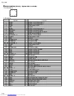
Traverse
mechanism
assembly
Feed motor
Spindle motor board
Bracket
G
G
G
H
D
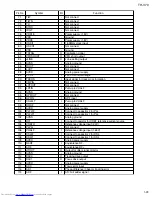
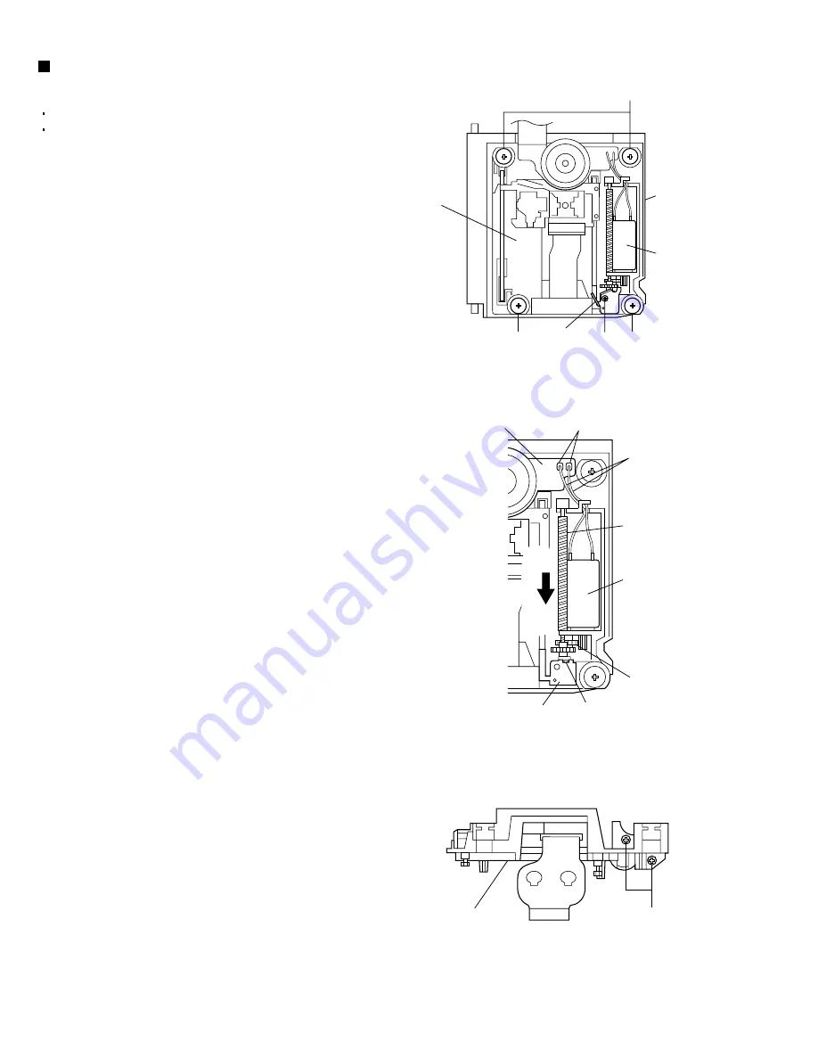
Feed motor
Feed gear M
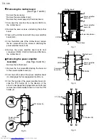
Remove the solders.
Claw
g
Traverse
mechanism assembly
Feed motor wire
Torsion spring
Lead screw
Mechanism
base
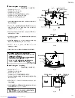
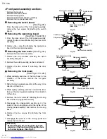
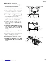
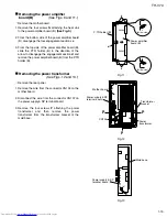
Removing the feed motor
(See Figs. 12 to 14.)
1.
2.
3.
4.
5.
6.
7.
8.
Remove the DVD servo board.
Remove the DVD traverse mechanism assembly.
Remove the four screws
G
attaching the traverse
mechanism assembly.
Take out the traverse mechanism assembly from
the mechanism base.
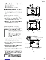
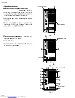
Remove the screw
D
attaching the bracket and
take out the bracket.
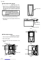
Disengage the claw
g
attaching the thrust spring
and take out the thrust spring.
Pull out the lead screw in the direction of arrow.
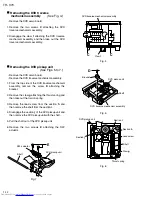
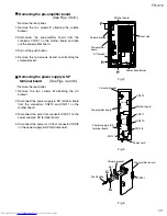
Remove the feed gear M.
Remove the feed motor wire that is soldered to the
spindle motor board.
Remove the two screws
H
attaching the feed motor
and take out the feed motor.
Содержание TH-V70
Страница 55: ...TH V70 1 55 M E M O ...


