
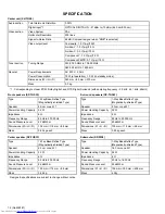

1-12 (No.MB187)
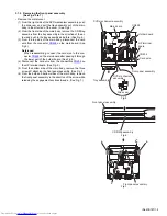
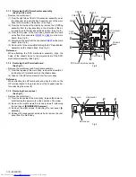
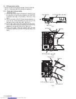
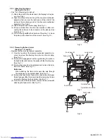
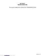
3.1.8 Removing the main board
(See Figs.12 and 13)
• Remove the metal cover.
(1) From the top side of the main body, disconnect the card
wires from the connectors (
CN341
,
CN422
to
CN428
) on
the main board.
[B/E/EN/EV/EE version]
(See Fig.12.)
(2) From the top side of the main body, disconnect the card
wires from the connectors (
CN422
to
CN428
) on the main
board.
[A version]
(See Fig.12.)
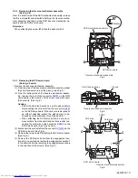
(3) Disconnect the wires from the connectors (
CN190
,
CN430
,
CN901
) on the main board. (See Fig.12.)
Reference:
After connecting the wires to the connectors (
CN190
,
CN901
), fix the wires with the wire holder. (See Fig.12.)
(4) Disconnect the power cord and wire from the connectors
(
CN950
,
CN953
) on the transformer board. (See Fig.12.)
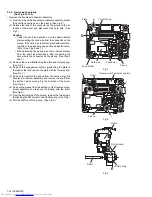
(5) Remove the three screws
J
and screw
J’
attaching the
main board on the chassis base. (See Fig.12.)
Reference:
When attaching the screw
J’
, attach the wire holder with
it. (See Fig.12.)
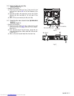
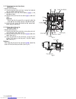
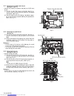
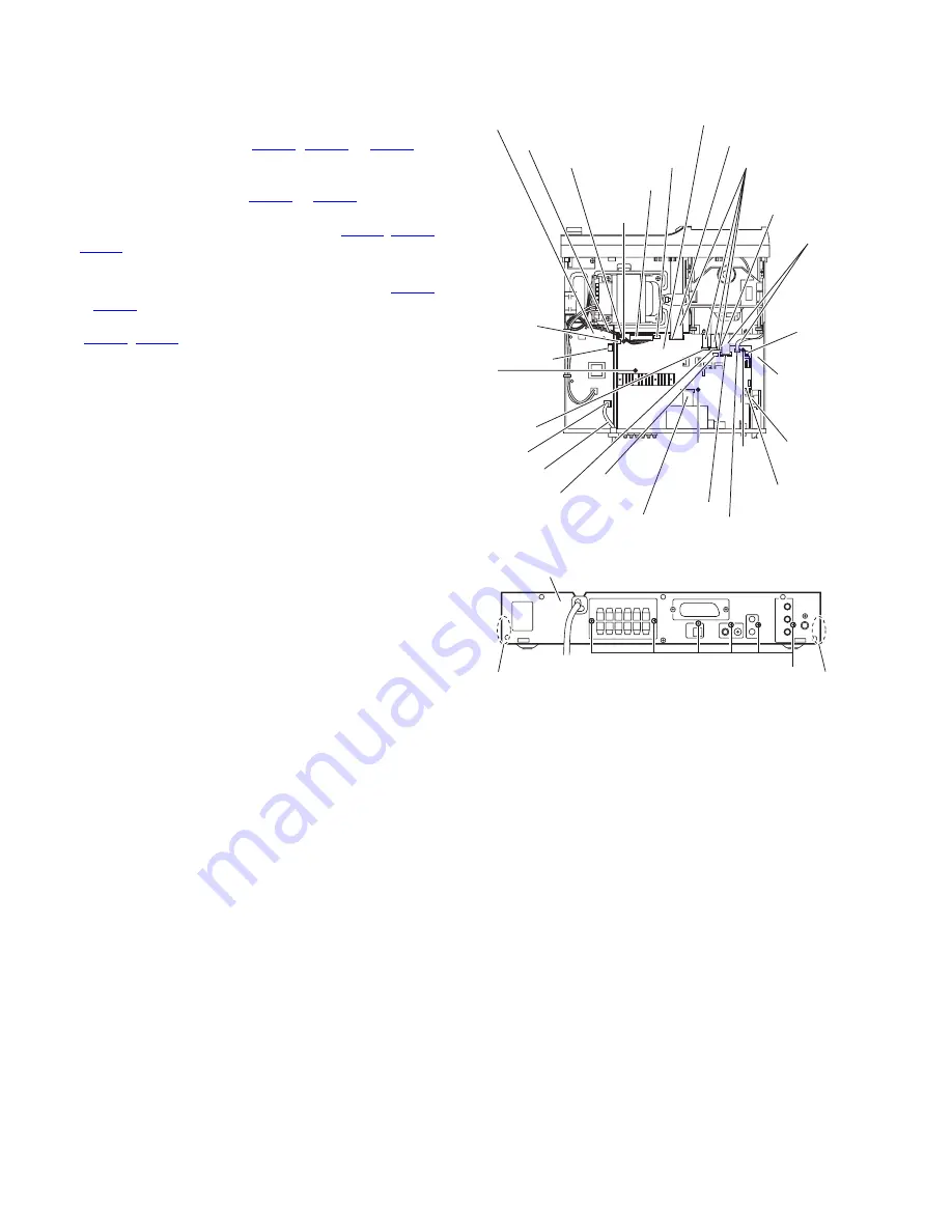
(6) From the back side of the main body, remove the six
screws
K
attaching the main board to the rear panel. (See
Fig.13.)
(7) Release the engagement sections
g
and remove the rear
panel together with the scart terminal board and tuner as-
sembly. (See Fig.13.)
(8) Take out the main board from the main body.
Reference:
When attaching the main board, align the hole on the main
board to the projections
h
of the chassis base before attaching
the screws
J
and
J’
. (See Fig.12.)
Fig.12
Fig.13
CN950
CN428
Main board
Transformer board
Wires
Card wires
Wire holder
CN953
J
CN190
CN901
J'
h
Power cord
h
J
Chassis
base
Card wire
CN427
CN425
Card wires
CN423
CN422
CN430
CN424
CN426
CN341
J
Rear panel
K
g
g


