


(No.MB338)1-13
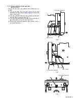
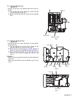
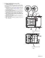
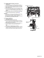
3.1.12 Removing the power transformer
(See Fig.16)
• Remove the rear cover, side panels(L)/(R), top cover assem-
bly, heat sink, main board, regulator board and transformer
board.
(1) From the reverse side of the transformer board, remove the
solders from the sections
f
on the transformer board.
(2) Remove the power transformer from the transformer
board.
Fig.16
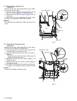
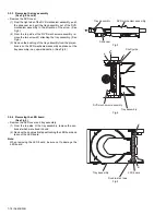
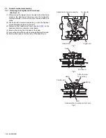
3.1.13 Removing the jack board and component board
(See Fig.17)
• Remove the rear cover, side panels(L)/(R), top cover assem-
bly, heat sink, main board and regulator board.
(1) From the back side of the main body, remove the two
screws
U
attaching the heat sink bracket.
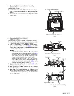
(2) From the top side of the main body, remove the screw
V
at-
taching the PWB holder and take out the PWB holder.
Reference:
When attaching the PWB holder, put the section
g
under
the hook of the bottom chassis.
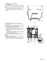
(3) Remove the screw
W
attaching the jack board and take out
the jack board with the component board.
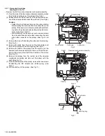
Reference:
• Remove the connector
CN631
on the component board
from the jack board as required.
• When attaching the jack board, attach it after putting a pro-
jection
h
of the bottom chassis in a hole of the jack board.
Fig.17
f
Transformer board
W
V
PWB holder
Jack board
g
h
Bottom chassis
Component board
CN631
Heat sink
bracket
U
U
Содержание SP-UXQD9S
Страница 32: ...1 32 No MB338 SECTION 5 TROUBLESHOOTING This service manual does not describe TROUBLESHOOTING ...
Страница 33: ... No MB338 1 33 ...
Страница 41: ...2 5 SHEET 4 ...
Страница 71: ...3 21 MEMO ...


