JVC RX-7042S Скачать руководство пользователя страница 31

29

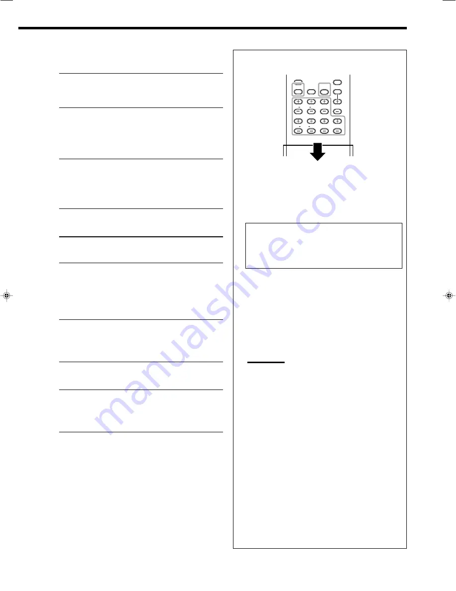
You can also use the remote control for adjusting the speaker
output level and center tone.

To adjust the speaker output level:
1. Press TEST to check if you can hear the sounds through

all the speakers at equal level.

Test tone comes out of the speakers in the following order.
• No test tone comes out of the speakers for which the

speaker setting is set to “NONE” (or “NO” for the
subwoofer).

FRNT L (Left front speaker) 

=

 CENTER (Center speaker) 

=

FRNT R (Right front speaker) 

=

SURR R (Right surround speaker) 

=

SBACK (surround back speaker)


=

SURR L (Left surround speaker) 

=

SUBWFR (Subwoofer) 

=

 (Back to the beginning)

2. Adjust the speaker output level.

 Adjustable range: –10 dB to +10 dB. “0 (dB)” is the initial
setting.
• To adjust the left front speaker, press FRONT L + or –.
• To adjust the center speaker, press or –.
• To adjust the right front speaker, press FRONT R + or –.
• To adjust the right surround speaker, press SURR R + or –.
• To adjust the surround back speaker, press S.BACK + or –.
• To adjust the left surround speaker, press SURR L + or –.
• To adjust the subwoofer, press or –.

Notes:

• When you press each button once, the current level for the

selected speaker appears on the display, and the test tone
comes out of the selected speaker.

• If no adjustment is done for about 4 seconds, the adjustment

mode for the selected speaker is canceled.

• If you don’t have the test tone emitted, adjustment for the

speaker output level is available. In this case, wait for about
4 seconds, after the adjustment is finished. Then the
adjustment mode for the selected speaker is canceled and
resumes the source indication on the display.

3. Repeat step 2 to adjust other speaker’s output levels.

4. Press TEST again to stop the test tone.

To adjust the center tone:
1. Press CENTER TONE repeatedly.

Adjustable range: 1 to 5. “3” is the initial setting, and
normally select this.

2. Wait for about 4 seconds, after the adjustment is finished.

The adjustment mode for the center tone is canceled and
automatically resumes the source indication on the display.

For DAP modes and Mono Film

• Once you have made an adjustment, it is memorized for each

mode.

EFFECT

Adjust the effect level. As the number
increases, the effect becomes stronger.
(Adjustable range: 

1

 to 

5. 

“3” is the initial

setting, and normally select this.)

ROOMSIZE

Adjust the virtual room size. As the number
increases, the interval between reflections
increases so that you will feel as if you were
in a larger room.
(Adjustable range: 

1

 to 

5. 

“3” is the initial

setting, and normally select this.)

LIVENESS

Adjust the liveness effect. As the number
increases, the attenuation level of reflections
over time decreases so that acoustics change
from “Dead” to “Live.”
(Adjustable range: 

1

 to 

5. 

“3” is the initial

setting, and normally select this.)

For Pro Logic II Music only

PNRM CNTRL

Select “ON” to add “wraparound” sound
effect with side-wall image. (Initial setting:
“OFF.”)

CNTR WIDTH

Adjust the center channel localization
between the center speaker and the left/right
front speakers. As the number increases, the
center channel sound moves toward the left
and right speakers. (Adjustable range: 

OFF

and

 1

 to 

7. 

“3” is the initial setting, and

normally select this.)

DIMENSION

Adjust the sound localization position. As the
number increases, the sound localization
moves towards forward from backward.
(Adjustable range: 

1

 to 

7. 

“4” is the initial

setting, and normally select this.)

For Neo:6  Music only

CNTR GAIN

Adjust the sound localization of the center
channel. As the number increases, center
channel will be localized clearly.
(Adjustable range: 

0

 to 

0.5. 

“0.2” is the initial

setting, and normally select this.)

TEST

L

R

FRONT

CENTER

L

R

SURR

S.BACK

SUBWFR

CENTER

TONE

27-29_7040[J]

04.1.21, 15:54

29

Содержание RX-7042S

Страница 1: ...he Model No and Serial No which are located either on the rear bottom or side of the cabinet Retain this information for future reference Model No Serial No LVT1170 001B J RX 7040B RX 7042S AUDIO VIDEO CONTROL RECEIVER INSTRUCTIONS ...

Страница 2: ...SER SERVICEABLE PARTS INSIDE REFER SERVICING TO QUALIFIED SERVICE PERSONNEL RISK OF ELECTRIC SHOCK DO NOT OPEN The lightning flash with arrowhead symbol within an equilateral triangle is intended to alert the user to the presence of uninsulated dangerous voltage within the product s enclosure that may be of sufficient magnitude to constitute a risk of electric shock to persons The exclamation poin...

Страница 3: ...g JVC s Audio Video Components 40 Operating Audio Components 40 Operating Video Components 41 Operating Other Manufacturers Video Equipment 42 Troubleshooting 45 Specifications 46 Introduction 2 Features 2 Precautions 2 Parts Identification 3 Getting Started 6 Checking the Supplied Accessories 6 Putting Batteries in the Remote Control 6 Connecting the FM and AM Antennas 6 Connecting the Speakers a...

Страница 4: ...oftware like Dolby Digital DTS Surround etc Thanks to the signal processing algorithms used by the high performance DSP you can enjoy a natural surround sound through the headphones COMPU LINK AV COMPU LINK remote control systems These COMPU LINK remote control systems allow you to operate other JVC s audio video components from this receiver Precautions General Be sure your hands are dry Turn the...

Страница 5: ...MODE button 16 40 t CD DISC button 40 y Sound adjustment buttons 15 18 28 29 40 u MUTING button 18 40 i VOLUME button 14 18 40 o DVD MENU button 41 43 SURR surround DSP OFF button 33 35 40 a CATV DBS CONT control button 42 VCR CONT control button 41 TAPE CDR CONT control button 41 s 10 keys for operating audio video components 40 43 10 keys for operating the tuner 20 40 d SLEEP button 18 40 1 2 3 ...

Страница 6: ...TT button 16 t MIDNIGHT MODE button 16 y INPUT DIGITAL button 16 u TUNER CONTROL buttons FM AM TUNING 5 buttons 19 FM AM PRESET 5 buttons 19 20 FM MODE button 20 MEMORY button 19 i SETTING button 23 o QUICK SPEAKER SETUP button 21 MULTI JOG control 21 23 27 PUSH SET button 21 23 27 a EXIT button 23 27 s ADJUST button 27 d ANALOG DIRECT button and lamp 17 SUBWOOFER OUT ON OFF SPEAKERS ON OFF PHONES...

Страница 7: ...HT LEFT RIGHT LEFT RIGHT LEFT CAUTION SPEAKER IMPEDANCE SINGLE USE See Instruction Manual For Connection 1 OR 2 8 16 1 AND 2 16 32 SUBWOOFER OUT FRONT SPEAKERS MONITOR OUT Y IN PLA TAPE CDR OUT REC IN PLAY OUT REC TV SOUND DBS IN DVD IN FRONT 1 2 3 4 5 6 7 8 9 p q w e r t See pages in parentheses for details 1 DIGITAL IN terminals 12 Coaxial DIGITAL 1 DVD Optical DIGITAL 2 CD DIGITAL 3 TV DIGITAL ...

Страница 8: ...ey match the polarity to and to Use the correct type of batteries Batteries that look similar may differ in voltage Always replace both batteries at the same time Do not expose batteries to heat or flame FM Antenna supplied Outdoor FM Antenna Cable not supplied Connecting the FM and AM Antennas FM antenna connections Connect the supplied FM antenna as temporary measure to the FM 75 Ω COAXIAL termi...

Страница 9: ...T CAUTION SPEAKER IMPEDANCE SURROUNDBACKSPEAKERS SINGLE USE See Instruction Manual For Connection SU 8 R To RIGHT ª terminal Connecting the subwoofer You can enhance the bass by connecting a subwoofer Connect the input jack of a powered subwoofer to the rear panel using a cable with RCA pin plugs not supplied SUBWOOFER OUT 1 2 3 Speaker connections 1 Twist and remove the insulation at the end of e...

Страница 10: ...istance from the listener However since in some places it may be difficult to fulfil this requirement this unit can adjust the delay time so that the sounds through all the speakers reach the listener with the same timing See page 24 Subwoofer When one surround back speaker is connected C L R LS RS SB SB SB Left Right Subwoofer Speaker layout Ideal speaker layout varies depending on the conditions...

Страница 11: ...N If you connect a sound enhancing device such as a graphic equalizer between the source components and this receiver the sound output through this receiver may be distorted CD player CD IN R L CD player To audio output TAPE CDR IN PLAY OUT REC R L R L Cassette deck To audio input To audio output Cassette deck You can connect either a cassette deck or a CD recorder to the TAPE CDR jacks When conne...

Страница 12: ...ack picture on the TV VCR Å To audio input ı To audio output Ç To S video output Î To composite video output To S video input Ï To composite video input Ì To component video output Notes When connecting a VCR to component video input jacks make the component video input setting VIDEO IN VCR correctly for AV COMPU LINK See page 26 for details When make the component video input setting for a VCR VI...

Страница 13: ...N SURR R L A B C D RIGHT LEFT DVD player When you connect a DVD player with its analog discrete output 5 1 channel reproduction jacks This connection is the best connection method for enjoying DVD Audio sounds When a DVD Audio disc is played back the original high quality sounds can be reproduced only using this connection Å To component video output ı To subwoofer output Ç To center channel audio...

Страница 14: ...ITAL 3 TV DIGITAL 4 CDR Digital coaxial cable not supplied between digital coaxial terminals Digital optical cable not supplied between digital optical terminals Before connecting a digital optical cable unplug the protective plug When the component has a digital optical output terminal connect it to the DIGITAL 2 CD DIGITAL 3 TV or DIGITAL 4 CDR terminal using a digital optical cable not supplied...

Страница 15: ...e external component When using the headphones you can listen to the front channel sounds left and right only The Surround modes see page 30 cannot be applied to DVD MULTI playback mode Daily Operational Procedure 1 Turn on the power See Turning On the Power below 2 Select the source See Selecting the Source to Play to the right 3 Adjust the volume See Adjusting the Volume on page 14 4 Select the ...

Страница 16: ... in SB Lights up when the surround back channel signal comes in Note When DVD MULTI is selected as the source L C R LFE LS and RS light up AM FM TAPE CDR CD Ex No sound comes out of the center speaker and surround back speakers though center channel and surround back channel signals are coming into this receiver How to understand the speaker and signal indicator illumination LFE SUBWFR L C R S LS ...

Страница 17: ...e can damage both the headphones and your hearing Before turning on the speakers again as its high volume may come out of the speakers Continued on the next page Remote NOT Turning On and Off the Subwoofer Sound You can cancel the subwoofer sound output even though you have connected a subwoofer and have set SUB WOOFER to YES see page 23 Press SUBWOOFER OUT ON OFF to cancel the subwoofer sound out...

Страница 18: ...O When using the remote control press ANALOG DIGITAL INPUT Each time you press the button the analog ANALOG and digital DGTL AUTO input modes alternate The DIGITAL AUTO indicator lights up on the display When selecting DGTL AUTO the following indicators indicate the digital signal format of the incoming signal Lights up when Linear PCM signals come in Lights up when Dolby Digital signals come in L...

Страница 19: ...ont speakers By using CC Converter you can obtain a natural sound field from both digital and analog sources Press CC CONVERTER so that the lamp on the button lights up Each time you press the button CC Converter turns on and off the lamp goes off alternately Note You cannot use this function while Analog Direct is in use If you turn on Analog Direct while this function is in use this function wil...

Страница 20: ...tment auto memory This receiver memorizes sound settings for each source when you turn off the power when you change the source and when you assign the source name see page 17 When you change the source the memorized settings for the newly selected source are automatically recalled The following can be stored for each source Analog digital input mode see pages 15 and 16 Midnight Mode see page 16 I...

Страница 21: ... 5 or to select a channel number while the channel number position is flashing 4 Press MEMORY again while the selected channel number is flashing on the display The selected channel number stops flashing The station is assigned to the selected channel number 5 Repeat steps 1 to 4 until you store all the stations you want To erase a stored preset station Storing a new station on a used number erase...

Страница 22: ...ption mode while receiving an FM broadcast You can store the FM reception mode for each preset station see page 19 While listening to an FM station press FM MODE Each time you press the button the FM reception mode alternates between AUTOMUTING and MODE MONO AUTOMUTING Normally select this When a program is broadcasted in stereo you will hear stereo sound when in monaural you will hear monaural so...

Страница 23: ...onfiguration 3 Press in MULTI JOG PUSH SET ROOM SIZE appears on the display then the initial room size setting appears 4 Turn MULTI JOG to select an appropriate room size to match to your listening room As you turn the jog the room size changes as follows To select your appropriate room size see Room size and the speaker distance on page 22 LARGE is the initial setting 5 Press in MULTI JOG PUSH SE...

Страница 24: ...e page SUB WOOFER Register your subwoofer 23 FRONT SPEAKER Register your front speaker size 23 CNTR SPEAKER Register your center speaker size 23 SURR SPEAKER Register your surround speaker size 23 SBACK SPEAKER Register your surround back speaker size 23 SBACK OUT Register the number of the connected surround back speakers 23 DIST UNIT Select the measuring unit for the speaker distance 24 FRNTL DI...

Страница 25: ...rs you cannot select LARGE for the center surround and surround back speakers If you have selected SMALL for the surround speakers you cannot select LARGE for the surround back speakers If you have selected NONE for the surround speakers the surround back speakers are fixed to NONE 7 Surround back speakers quantity SBACK OUT Select the number of the surround back speakers connected SBACK OUT 1SPK ...

Страница 26: ...r or not the bass elements of the front speaker channels are transmitted through the subwoofer regardless of the front speaker size setting either SMALL or LARGE Select one of the following S WFR LFE Select to emit only the LFE signals while playing Dolby Digital or DTS software or the bass elements of the SMALL front speakers while playing any source other than the above S WFR LFE MAIN Select to ...

Страница 27: ...nected to the digital coaxial terminal DIGITAL 1 Following setting is available DVD initial setting CD TV or DBS CDR VCR If you have changed the source name from TV to DBS DBS appears see page 17 7 Low frequency effect attenuator LFE ATTENUATE If the bass sound is distorted while playing back software encoded with Dolby Digital or DTS set the LFE level to eliminate distortion This function takes e...

Страница 28: ...he currently selected source is recalled when the source is selected To cancel the One Touch Operation Set One Touch Operation to OFF so that the ONE TOUCH OPERATION indicator goes off from the display 7 Digital optical terminals DGTL IN OPTICAL Set the components connected to the digital optical terminals DIGITAL 2 4 As you turn MULTI JOG the digital optical input terminals are set to used for fo...

Страница 29: ...round sound effect with side wall image 29 CNTR WIDTH 2 Adjust the center channel localization between the center speaker and the left right front speakers 29 DIMENSION 2 Adjust sound localization position 29 CNTR GAIN 3 Adjust sound localization of the center channel 29 Notes 1 Adjustable when one of the DAP modes or Mono Film see pages 34 and 35 is in use 2 Adjustable when Pro Logic II Music see...

Страница 30: ...able parameters You can adjust the following parameters For Surround and DSP modes when the center speaker is connected This setting is common to all surround modes and is memorized separately for DSP modes CTR TONE Adjust the center tone As the number increases the dialogue becomes clearer so that the human voices change from soft to sharp Adjustable range 1 to 5 3 is the initial setting and norm...

Страница 31: ...ress CENTER TONE repeatedly Adjustable range 1 to 5 3 is the initial setting and normally select this 2 Wait for about 4 seconds after the adjustment is finished The adjustment mode for the center tone is canceled and automatically resumes the source indication on the display For DAP modes and Mono Film Once you have made an adjustment it is memorized for each mode EFFECT Adjust the effect level A...

Страница 32: ...utoff frequency of the surround treble at 20 kHz compared to 7 kHz for Dolby Pro Logic As such the sound movement and being there feeling are enhanced much more than Dolby Pro Logic Dolby Digital EX Dolby Digital EX DOLBY D EX is a digital surround encoding format that adds the third surround channels called surround back Compared to the conventional Dolby Digital 5 1CH these newly added surround ...

Страница 33: ...red to Dolby Digital the DTS Digital Surround format has a lower audio compression rate which enables it to add breadth and depth to the sounds reproduced As such DTS Digital Surround features natural solid and clear sound When EX ES setting is set to ON DTS Neo 6 DTS NEO 6 is applied while playing back multi channel DTS software It creates the same surround ambience as 6 1 channel software does D...

Страница 34: ...24 Matrix OFF DTS NONE AUTO ON DTS VIRTUAL SB 2 3 OFF DTS DTS DTS 96 24 3 2 2 2 2SPK 1SPK ON DTS NEO 6 3 AUTO OFF DTS NONE ON DTS VIRTUAL SB 2 3 AUTO OFF DTS DTS 3 1 2 1 3 0 1 0 2SPK 1SPK NONE AUTO ON OFF DTS DTS Dual Mono 2SPK 1SPK NONE AUTO ON OFF DUAL MONO Incoming Signal Type Available Surround Mode Analog PCM Dolby Surround Dolby Digital 2 0 DTS 2 0 PLII MOVIE PLII MUSIC PRO LOGIC NEO 6 CINMA...

Страница 35: ...e to which the EX ES 7 1 channel reproduction cannot be applied you can adjust the setting and store in memory but reproduction channels will remain unchanged When the surround speakers are deactivated you cannot activate this setting and NO SURR SP appears on the display Activating the surround modes automatically You can enjoy the Surround mode simply by selecting the source with digital input s...

Страница 36: ...ound field in your listening room HALL 1 Reproduces the spatial feeling of a large shoebox shaped hall designed primarily for classical concerts Its seating capacity is about 2000 HALL 2 Reproduces the spatial feeling of a large vineyard shaped hall designed primarily for classical concerts Its seating capacity is about 2000 LIVE CLUB Reproduces the spatial feeling of a live music club with a low ...

Страница 37: ...gital signal to another digital signal type MONO FILM is canceled and an appropriate Surround mode is activated Activating the DSP Modes Activating one of the DSP modes for a source automatically recalls the memorized settings and adjustments see pages 21 to 29 You can also use the buttons on the remote control for the same functions 1 Select and play any source excluding DVD MULTI 2 Press DSP rep...

Страница 38: ...When using a headphones you can listen to the front channels left and right only therefore 3D Headphone 3D H PHONE mode is not valid for DVD MULTI playback mode Connection diagram Å To component video output ı To subwoofer output Ç To center channel audio output Î To S video output To composite video output Ï To left right front channel audio output Ì To left right surround channel audio output No...

Страница 39: ...tarts the cassette deck starts recording When the play ends the cassette deck enters recording pause and stops about 4 seconds later Notes During synchronized recording the selected source cannot be changed If the power of any component is shut off during synchronized recording the COMPU LINK remote control system may not operate properly In this case you must start again from the beginning COMPUL...

Страница 40: ...omposite video and component video and the signals coming into this receiver through one type of video jacks can output only through the jack of the same type So you need to connect the VCR and or DVD player to the TV using one of the following three ways When using the AV COMPU LINK remote control system set the component video input for the DVD player and the VCR correctly see Setting the compon...

Страница 41: ...g playback on the DVD player you can enjoy the DVD playback without setting other switches manually When the DVD player is connected through the analog input jacks on this receiver and analog input is selected the receiver automatically turns on and changes the source to DVD or DVD MULTI When the DVD player is connected through the digital input terminal on this receiver and digital input is selec...

Страница 42: ...sing the supplied remote control You need to connect JVC s audio components through the COMPU LINK SYNCHRO jacks see page 37 in addition to the connections using cables with RCA pin plugs see page 9 Aim the remote control directly at the remote sensor on the receiver If you use the buttons on the front panel to choose a source the remote control will not operate that source To operate a source wit...

Страница 43: ...ing VCR or VCR CONT you can perform the following operations on a VCR 3 Start playing REW Rewind the tape FF Fast forward the tape 7 Stop playing and recording or rewind or fast forward the tape 8 Pause playing or recording To resume press 3 DVD MENU CHANNEL Change the TV channels on a VCR 1 9 10 RETURN 0 100 10 Select the TV channels on a VCR The 10 RETURN button will function as the ENTER button...

Страница 44: ...n as the ENTER button if your TV requires pressing ENTER after selecting a channel number Notes All the functions listed above may not be assigned to the buttons for some TVs If you cannot change the channels of some TVs by pressing 10 keys press CHANNEL for changing the channels To change the transmittable signals for operating a CATV converter or DBS tuner 1 Press and hold CATV DBS 2 Press CATV ...

Страница 45: ...or track number 30 press 10 10 then 10 or press 10 10 10 then 0 After pressing DVD or DVD MULTI these buttons can be used for the DVD menu operations Note For detailed menu operations refer to the instructions supplied with the discs or the DVD player To change the transmittable signals for operating another manufacturer s VCR 1 Press and hold VCR 2 Press VCR 3 Enter manufacturer s code using butt...

Страница 46: ...52 Teknica 53 54 Toshiba 55 Zenith 56 For CATV converter Manufacturer Codes General Instrument 01 Gemini 02 Hamlin 03 04 05 06 Jerrold 07 08 09 10 11 12 13 14 15 Macom 16 17 18 Magnavox 19 Oak 20 21 22 Panasonic 23 24 Philips 25 26 27 28 29 30 Pioneer 31 32 S Atlanta 33 34 35 Samsung 36 Tocom 37 Zenith 38 39 Manufacturer Codes Echostar 40 General Instrument 41 Hitachi 42 Hughes 43 Panasonic 44 Pri...

Страница 47: ...eplace batteries See page 6 Select the correct remote control operation mode See pages 40 and 41 POSSIBLE CAUSE The power cord is not plugged in Speaker signal cables are not connected The SPEAKERS ON OFF 1 and SPEAKERS ON OFF 2 buttons are not set correctly An incorrect source is selected Muting is activated An incorrect input mode analog or digital is selected Speaker signal cables are not conne...

Страница 48: ...HF 78 IHF DVD IN VCR IN TV SOUND DBS IN 87 dB 80 dB CD IN TAPE CDR IN 87 dB 80 dB Frequency Response 8 Ω DVD IN VCR IN TV SOUND DBS IN 20 Hz to 100 kHz 1 dB 3 dB CD IN TAPE CDR IN 20 Hz to 100 kHz 1 dB 3 dB Bass Boost 6 dB 1 0 dB at 100 Hz Equalization 63 Hz 250 Hz 1 kHz 4 kHz 16 kHz 8 dB in 2 dB steps Video Video Input Sensitivity Impedance Composite Video DVD IN VCR IN TV SOUND DBS IN 1 V p p 75...

Страница 49: ...cleaning 4 Damage that occurs in shipment due to act of God and cosmetic damage 5 Signal reception problems and failures due to line power surge 6 Video Pick up Tubes CCD Image Sensor Cartridge Stylus Needle are covered for 90 days from the date of purchase 7 Batteries except that Rechargeable Batteries are covered for 90 days from the date of purchase There are no express warranties except as lis...

Страница 50: ...rized servicer or visit our website at www JVC com Remember to retain your Bill of Sale for Warranty Service Do not service the television yourself Caution To prevent electrical shock do not open the cabinet There are no user serviceable parts inside Please refer to qualified service personnel for repairs Accessories To purchase accessories for your JVC product please call toll free 1 800 882 2345...

Страница 51: ...EN 0104MWMMDWJEIN 2004 VICTOR COMPANY OF JAPAN LIMITED VICTOR COMPANY OF JAPAN LIMITED RX 7040B RX 7042S AUDIO VIDEO CONTROL RECEIVER ...

Страница 52: ...LVT1170 002A C RX 7040B RX 7042S INSTRUCTIONS MANUEL D INSTRUCTIONS AUDIO VIDEO CONTROL RECEIVER RECEPTEUR DE COMMANDE AUDIO VIDEO English Français ...

Страница 53: ...SER SERVICEABLE PARTS INSIDE REFER SERVICING TO QUALIFIED SERVICE PERSONNEL RISK OF ELECTRIC SHOCK DO NOT OPEN The lightning flash with arrowhead symbol within an equilateral triangle is intended to alert the user to the presence of uninsulated dangerous voltage within the product s enclosure that may be of sufficient magnitude to constitute a risk of electric shock to persons The exclamation poin...

Страница 54: ...ating JVC s Audio Video Components 40 Operating Audio Components 40 Operating Video Components 41 Operating Other Manufacturers Video Equipment 42 Troubleshooting 45 Specifications 46 Introduction 2 Features 2 Precautions 2 Parts Identification 3 Getting Started 6 Checking the Supplied Accessories 6 Putting Batteries in the Remote Control 6 Connecting the FM and AM Antennas 6 Connecting the Speake...

Страница 55: ...ti channel software like Dolby Digital DTS Surround etc Thanks to the signal processing algorithms used by the high performance DSP you can enjoy a natural surround sound through the headphones COMPU LINK AV COMPU LINK remote control systems These COMPU LINK remote control systems allow you to operate other JVC s audio video components from this receiver Precautions General Be sure your hands are ...

Страница 56: ...GHT MODE button 16 40 t CD DISC button 40 y Sound adjustment buttons 18 28 29 40 u MUTING button 18 40 i VOLUME button 14 18 40 o DVD MENU button 41 43 SURR surround DSP OFF button 33 35 40 a CATV DBS CONT control button 42 VCR CONT control button 41 TAPE CDR CONT control button 41 s 10 keys for operating audio video components 40 43 10 keys for operating the tuner 20 40 d SLEEP button 18 40 1 2 3...

Страница 57: ...T ATT button 16 t MIDNIGHT MODE button 16 y INPUT DIGITAL button 16 u TUNER CONTROL buttons FM AM TUNING 5 buttons 19 FM AM PRESET 5 buttons 19 20 FM MODE button 20 MEMORY button 19 i SETTING button 23 o QUICK SPEAKER SETUP button 21 MULTI JOG control 21 23 27 PUSH SET button 21 23 27 a EXIT button 23 27 s ADJUST button 27 d ANALOG DIRECT button and lamp 17 SUBWOOFER OUT ON OFF SPEAKERS ON OFF PHO...

Страница 58: ... RIGHT LEFT RIGHT LEFT RIGHT LEFT CAUTION SPEAKER IMPEDANCE SINGLE USE See Instruction Manual For Connection 1 OR 2 8 16 1 AND 2 16 32 SUBWOOFER OUT FRONT SPEAKERS MONITOR OUT Y IN PLA TAPE CDR OUT REC IN PLAY OUT REC TV SOUND DBS IN DVD IN FRONT 1 2 3 4 5 6 7 8 9 p q w e r t See pages in parentheses for details 1 DIGITAL IN terminals 12 Coaxial DIGITAL 1 DVD Optical DIGITAL 2 CD DIGITAL 3 TV DIGI...

Страница 59: ...o they match the polarity to and to Use the correct type of batteries Batteries that look similar may differ in voltage Always replace both batteries at the same time Do not expose batteries to heat or flame FM Antenna supplied Outdoor FM Antenna Cable not supplied Connecting the FM and AM Antennas FM antenna connections Connect the supplied FM antenna as temporary measure to the FM 75 Ω COAXIAL t...

Страница 60: ... LEFT CAUTION SPEAKER IMPEDANCE SURROUNDBACKSPEAKERS SINGLE USE See Instruction Manual For Connection SU 8 R To RIGHT ª terminal Connecting the subwoofer You can enhance the bass by connecting a subwoofer Connect the input jack of a powered subwoofer to the rear panel using a cable with RCA pin plugs not supplied SUBWOOFER OUT 1 2 3 Speaker connections 1 Twist and remove the insulation at the end ...

Страница 61: ...tance from the listener However since in some places it may be difficult to fulfil this requirement this unit can adjust the delay time so that the sounds through all the speakers reach the listener with the same timing See page 24 Subwoofer When one surround back speaker is connected C L R LS RS SB SB SB Left Right Subwoofer Speaker layout Ideal speaker layout varies depending on the conditions o...

Страница 62: ...UTION If you connect a sound enhancing device such as a graphic equalizer between the source components and this receiver the sound output through this receiver may be distorted CD player CD IN R L CD player To audio output TAPE CDR IN PLAY OUT REC R L R L Cassette deck To audio input To audio output Cassette deck You can connect either a cassette deck or a CD recorder to the TAPE CDR jacks When c...

Страница 63: ...layback picture on the TV VCR Å To audio input ı To audio output Ç To S video output Î To composite video output To S video input Ï To composite video input Ì To component video output Notes When connecting a VCR to component video input jacks make the component video input setting VIDEO IN VCR correctly for AV COMPU LINK See page 26 for details When make the component video input setting for a VC...

Страница 64: ...VD IN SURR R L A B C D RIGHT LEFT DVD player When you connect a DVD player with its analog discrete output 5 1 channel reproduction jacks This connection is the best connection method for enjoying DVD Audio sounds When a DVD Audio disc is played back the original high quality sounds can be reproduced only using this connection Å To component video output ı To subwoofer output Ç To center channel a...

Страница 65: ... DIGITAL 3 TV DIGITAL 4 CDR Digital coaxial cable not supplied between digital coaxial terminals Digital optical cable not supplied between digital optical terminals Before connecting a digital optical cable unplug the protective plug When the component has a digital optical output terminal connect it to the DIGITAL 2 CD DIGITAL 3 TV or DIGITAL 4 CDR terminal using a digital optical cable not supp...

Страница 66: ...n the external component When using the headphones you can listen to the front channel sounds left and right only The Surround modes see page 30 cannot be applied to DVD MULTI playback mode Daily Operational Procedure 1 Turn on the power See Turning On the Power below 2 Select the source See Selecting the Source to Play to the right 3 Adjust the volume See Adjusting the Volume on page 14 4 Select ...

Страница 67: ...depends on the speaker setting for details see Setting the speakers on page 23 The frames of L C R LS RS and SB light up when the corresponding speakers are set to LARGE or SMALL and when the speaker is required for the Surround DSP mode currently selected When SUB WOOFER is set to YES SUBWFR lights up see page 23 All three frames on the row of SB are not used at the same time When SBACK OUT is se...

Страница 68: ...olume can damage both the headphones and your hearing Before turning on the speakers again as its high volume may come out of the speakers Continued on the next page Remote NOT Turning On and Off the Subwoofer Sound You can cancel the subwoofer sound output even though you have connected a subwoofer and have set SUB WOOFER to YES see page 23 Press SUBWOOFER OUT ON OFF to cancel the subwoofer sound...

Страница 69: ... AUTO When using the remote control press ANALOG DIGITAL INPUT Each time you press the button the analog ANALOG and digital DGTL AUTO input modes alternate The DIGITAL AUTO indicator lights up on the display When selecting DGTL AUTO the following indicators indicate the digital signal format of the incoming signal Lights up when Linear PCM signals come in Lights up when Dolby Digital signals come ...

Страница 70: ...e front speakers By using CC Converter you can obtain a natural sound field from both digital and analog sources Press CC CONVERTER so that the lamp on the button lights up Each time you press the button CC Converter turns on and off the lamp goes off alternately Note You cannot use this function while Analog Direct is in use If you turn on Analog Direct while this function is in use this function...

Страница 71: ...djustment auto memory This receiver memorizes sound settings for each source when you turn off the power when you change the source and when you assign the source name see page 17 When you change the source the memorized settings for the newly selected source are automatically recalled The following can be stored for each source Analog digital input mode see pages 15 and 16 Midnight Mode see page ...

Страница 72: ...ESET 5 or to select a channel number while the channel number position is flashing 4 Press MEMORY again while the selected channel number is flashing on the display The selected channel number stops flashing The station is assigned to the selected channel number 5 Repeat steps 1 to 4 until you store all the stations you want To erase a stored preset station Storing a new station on a used number e...

Страница 73: ...reception mode while receiving an FM broadcast You can store the FM reception mode for each preset station see page 19 While listening to an FM station press FM MODE Each time you press the button the FM reception mode alternates between AUTOMUTING and MODE MONO AUTOMUTING Normally select this When a program is broadcasted in stereo you will hear stereo sound when in monaural you will hear monaura...

Страница 74: ...er configuration 3 Press in MULTI JOG PUSH SET ROOM SIZE appears on the display then the initial room size setting appears 4 Turn MULTI JOG to select an appropriate room size to match to your listening room As you turn the jog the room size changes as follows To select your appropriate room size see Room size and the speaker distance on page 22 LARGE is the initial setting 5 Press in MULTI JOG PUS...

Страница 75: ...do See page SUB WOOFER Register your subwoofer 23 FRONT SPEAKER Register your front speaker size 23 CNTR SPEAKER Register your center speaker size 23 SURR SPEAKER Register your surround speaker size 23 SBACK SPEAKER Register your surround back speaker size 23 SBACK OUT Register the number of the connected surround back speakers 23 DIST UNIT Select the measuring unit for the speaker distance 24 FRN...

Страница 76: ...nnot select LARGE for the center surround and surround back speakers If you have selected SMALL for the surround speakers you cannot select LARGE for the surround back speakers If you have selected NONE for the surround speakers the surround back speakers are fixed to NONE 7 Surround back speakers quantity SBACK OUT Select the number of the surround back speakers connected SBACK OUT 1SPK Select to...

Страница 77: ...other words you can determine whether or not the bass elements of the front speaker channels are transmitted through the subwoofer regardless of the front speaker size setting either SMALL or LARGE Select one of the following S WFR LFE Select to emit only the LFE signals while playing Dolby Digital or DTS software or the bass elements of the SMALL front speakers while playing any source other than...

Страница 78: ...t the component connected to the digital coaxial terminal DIGITAL 1 Following setting is available DVD initial setting CD TV or DBS CDR VCR If you have changed the source name from TV to DBS DBS appears see page 17 7 Low frequency effect attenuator LFE ATTENUATE If the bass sound is distorted while playing back software encoded with Dolby Digital or DTS set the LFE level to eliminate distortion Th...

Страница 79: ...or the currently selected source is recalled when the source is selected To cancel the One Touch Operation Set One Touch Operation to OFF so that the ONE TOUCH OPERATION indicator goes off from the display 7 Digital optical terminals DGTL IN OPTICAL Set the components connected to the digital optical terminals DIGITAL 2 4 As you turn MULTI JOG the digital optical input terminals are set to used fo...

Страница 80: ...raparound sound effect with side wall image 29 CNTR WIDTH 2 Adjust the center channel localization between the center speaker and the left right front speakers 29 DIMENSION 2 Adjust sound localization position 29 CNTR GAIN 3 Adjust sound localization of the center channel 29 Notes 1 Adjustable when one of the DAP modes or Mono Film see pages 34 and 35 is in use 2 Adjustable when Pro Logic II Music...

Страница 81: ...R WIDTH CNTR GAIN 7 Adjustable parameters You can adjust the following parameters For Surround and DSP modes when the center speaker is connected This setting is common to all surround modes and is memorized separately for DSP modes CTR TONE Adjust the center tone As the number increases the dialogue becomes clearer so that the human voices change from soft to sharp Adjustable range 1 to 5 3 is th...

Страница 82: ... 1 Press CENTER TONE repeatedly Adjustable range 1 to 5 3 is the initial setting and normally select this 2 Wait for about 4 seconds after the adjustment is finished The adjustment mode for the center tone is canceled and automatically resumes the source indication on the display For DAP modes and Mono Film Once you have made an adjustment it is memorized for each mode EFFECT Adjust the effect lev...

Страница 83: ...he cutoff frequency of the surround treble at 20 kHz compared to 7 kHz for Dolby Pro Logic As such the sound movement and being there feeling are enhanced much more than Dolby Pro Logic Dolby Digital EX Dolby Digital EX DOLBY D EX is a digital surround encoding format that adds the third surround channels called surround back Compared to the conventional Dolby Digital 5 1CH these newly added surro...

Страница 84: ...ompared to Dolby Digital the DTS Digital Surround format has a lower audio compression rate which enables it to add breadth and depth to the sounds reproduced As such DTS Digital Surround features natural solid and clear sound When EX ES setting is set to ON DTS Neo 6 DTS NEO 6 is applied while playing back multi channel DTS software It creates the same surround ambience as 6 1 channel software do...

Страница 85: ... 96 24 Matrix OFF DTS NONE AUTO ON DTS VIRTUAL SB 2 3 OFF DTS DTS DTS 96 24 3 2 2 2 2SPK 1SPK ON DTS NEO 6 3 AUTO OFF DTS NONE ON DTS VIRTUAL SB 2 3 AUTO OFF DTS DTS 3 1 2 1 3 0 1 0 2SPK 1SPK NONE AUTO ON OFF DTS DTS Dual Mono 2SPK 1SPK NONE AUTO ON OFF DUAL MONO Incoming Signal Type Available Surround Mode Analog PCM Dolby Surround Dolby Digital 2 0 DTS 2 0 PLII MOVIE PLII MUSIC PRO LOGIC NEO 6 C...

Страница 86: ...s one to which the EX ES 7 1 channel reproduction cannot be applied you can adjust the setting and store in memory but reproduction channels will remain unchanged When the surround speakers are deactivated you cannot activate this setting and NO SURR SP appears on the display Activating the surround modes automatically You can enjoy the Surround mode simply by selecting the source with digital inp...

Страница 87: ...ic sound field in your listening room HALL 1 Reproduces the spatial feeling of a large shoebox shaped hall designed primarily for classical concerts Its seating capacity is about 2000 HALL 2 Reproduces the spatial feeling of a large vineyard shaped hall designed primarily for classical concerts Its seating capacity is about 2000 LIVE CLUB Reproduces the spatial feeling of a live music club with a ...

Страница 88: ...l digital signal to another digital signal type MONO FILM is canceled and an appropriate Surround mode is activated Activating the DSP Modes Activating one of the DSP modes for a source automatically recalls the memorized settings and adjustments see pages 21 to 29 You can also use the buttons on the remote control for the same functions 1 Select and play any source excluding DVD MULTI 2 Press DSP...

Страница 89: ... 16 When using a headphones you can listen to the front channels left and right only therefore 3D Headphone 3D H PHONE mode is not valid for DVD MULTI playback mode Connection diagram Å To component video output ı To subwoofer output Ç To center channel audio output Î To S video output To composite video output Ï To left right front channel audio output Ì To left right surround channel audio outpu...

Страница 90: ...ay starts the cassette deck starts recording When the play ends the cassette deck enters recording pause and stops about 4 seconds later Notes During synchronized recording the selected source cannot be changed If the power of any component is shut off during synchronized recording the COMPU LINK remote control system may not operate properly In this case you must start again from the beginning CO...

Страница 91: ...eo composite video and component video and the signals coming into this receiver through one type of video jacks can output only through the jack of the same type So you need to connect the VCR and or DVD player to the TV using one of the following three ways When using the AV COMPU LINK remote control system set the component video input for the DVD player and the VCR correctly see Setting the co...

Страница 92: ...n the VCR or on the remote control So you can get the same result One Touch DVD Play Simply by starting playback on the DVD player you can enjoy the DVD playback without setting other switches manually When the DVD player is connected through the analog input jacks on this receiver and analog input is selected the receiver automatically turns on and changes the source to DVD or DVD MULTI When the ...

Страница 93: ...ts using the supplied remote control You need to connect JVC s audio components through the COMPU LINK SYNCHRO jacks see page 37 in addition to the connections using cables with RCA pin plugs see page 9 Aim the remote control directly at the remote sensor on the receiver If you use the buttons on the front panel to choose a source the remote control will not operate that source To operate a source...

Страница 94: ...ressing VCR or VCR CONT you can perform the following operations on a VCR 3 Start playing REW Rewind the tape FF Fast forward the tape 7 Stop playing and recording or rewind or fast forward the tape 8 Pause playing or recording To resume press 3 DVD MENU CHANNEL Change the TV channels on a VCR 1 9 10 RETURN 0 100 10 Select the TV channels on a VCR The 10 RETURN button will function as the ENTER bu...

Страница 95: ...ction as the ENTER button if your TV requires pressing ENTER after selecting a channel number Notes All the functions listed above may not be assigned to the buttons for some TVs If you cannot change the channels of some TVs by pressing 10 keys press CHANNEL for changing the channels To change the transmittable signals for operating a CATV converter or DBS tuner 1 Press and hold CATV DBS 2 Press C...

Страница 96: ... 0 For track number 30 press 10 10 then 10 or press 10 10 10 then 0 After pressing DVD or DVD MULTI these buttons can be used for the DVD menu operations Note For detailed menu operations refer to the instructions supplied with the discs or the DVD player To change the transmittable signals for operating another manufacturer s VCR 1 Press and hold VCR 2 Press VCR 3 Enter manufacturer s code using ...

Страница 97: ...nic 52 Teknica 53 54 Toshiba 55 Zenith 56 For CATV converter Manufacturer Codes General Instrument 01 Gemini 02 Hamlin 03 04 05 06 Jerrold 07 08 09 10 11 12 13 14 15 Macom 16 17 18 Magnavox 19 Oak 20 21 22 Panasonic 23 24 Philips 25 26 27 28 29 30 Pioneer 31 32 S Atlanta 33 34 35 Samsung 36 Tocom 37 Zenith 38 39 Manufacturer Codes Echostar 40 General Instrument 41 Hitachi 42 Hughes 43 Panasonic 44...

Страница 98: ...on Replace batteries See page 6 Select the correct remote control operation mode See pages 40 and 41 POSSIBLE CAUSE The power cord is not plugged in Speaker signal cables are not connected The SPEAKERS ON OFF 1 and SPEAKERS ON OFF 2 buttons are not set correctly An incorrect source is selected Muting is activated An incorrect input mode analog or digital is selected Speaker signal cables are not c...

Страница 99: ...Signal to Noise Ratio 66 IHF 78 IHF DVD IN VCR IN TV SOUND DBS IN 87 dB 80 dB CD IN TAPE CDR IN 87 dB 80 dB Frequency Response 8 Ω DVD IN VCR IN TV SOUND DBS IN 20 Hz to 100 kHz 1 dB 3 dB CD IN TAPE CDR IN 20 Hz to 100 kHz 1 dB 3 dB Bass Boost 6 dB 1 0 dB at 100 Hz Equalization 63 Hz 250 Hz 1 kHz 4 kHz 16 kHz 8 dB in 2 dB steps Video Video Input Sensitivity Impedance Composite Video DVD IN VCR IN ...

Страница 100: ...EN FR 0204MWMMDWJEIN 2004 VICTOR COMPANY OF JAPAN LIMITED VICTOR COMPANY OF JAPAN LIMITED RX 7040B RX 7042S AUDIO VIDEO CONTROL RECEIVER ...

Отзывы: